

µSIGAMP
This 1/3 height micro module provides a two independant channels for a signal amplifier which is very similar to the 2SIGNALAMP module.
This module needs to be installed on the µBASE module!
Module power consumption: ? mA
Inputs
- IN 1, IN 2 - inputs for each of the amplifying channels
Outputs
- OUT 1, OUT 2 - outputs for each of the amplifying channels
Controls
- LEVEL 1, LEVEL 2 Pot - Level control for how much the relevant signal will be amplified.
Patch Suggestions
Some modules in the AE system produce very low volume or signal levels, eg. GRAINS, VCO, (particularly the triangle wave), and sometimes the SOLINA . With the SIGNALAMP you can increase the signal of these modules so they can hold their own in a mix with other much stronger signals. Also can be useful to boost heavily filtered audio....

µ2VCA
This 1/3 height micro module provides a two channel VCA similar to the 4VCA module.
This module needs to be installed on the µBASE module!
Module power consumption: ? mA
Inputs
- IN 1 - Input signal for channel 1
- CV 1 - level voltage control for channel 1
- IN 2 - Input signal for channel 2
- CV 2 - level voltage control for channel 2
Outputs
- OUT 1 - output of channel 1
- OUT 2 - output of channel 2
Controls
- Audio / DC/CV switches - switch between audio and CV signals for either channel.
Patch Suggestions
This can be used for attenuating Audio or CV signals. Check out the patch suggestions for 2VCA and 4VCA.

µ4BUFFER
This 1/3 height micro module provides a buffered 4 channel multiple. This can be used for multiplying cv, trigger and gate signals without voltage loss. One input signal will be routed to two duplicate outputs.
This module needs to be installed on the µBASE module!
Module power consumption: ? mA
Inputs
- IN 1, 2, 3, 4 - Inputs for each of the 4 buffer channels
Outputs
- OUT 1, 2, 3, 4 - Two outputs for each of the 4 channels.
Patch Suggestions
While this module seems to provide similar functionality as the 4BUFFER module, it is missing the linking feature. So if you want to multiply one input signal to many outputs, then you need to patch it internally, eg.:
- Patch an input signal to IN1
- Patch OUT1a to IN2
- Patch OUT1b to IN3
Now you have 4 outgoing copies of the incoming signal from OUT2 and OUT3.

µ4LOGIC
This 1/3 height micro module provides various logic gates and inverted functions. There are 4 channels for logic operations, two channels for two signals to be combined using either NAND, AND or XOR logic and two channels for inverting a signal.
This module needs to be installed on the µBASE module!
Module power consumption: ? mA
This module works exactly like the bigger LOGIC module. Please check its wiki page for more information, and patch suggestions.

µATTENUVERT
This 1/3 height micro module provides a single attenuverter function whereby you can offset an incoming signal and attenuate it at the same time.
This module needs to be installed on the µBASE module!
Module power consumption: ? mA
Inputs
- IN - The incoming CV signal
Outputs
- OUT The signal after it's been offset by the offset knob and attenuated by the level knob
Controls
- OFFSET - This sets the amount of voltage alteration applied to the input signal.
- LEVEL - This controls the incoming signal amount, before being added to the offset.
Patch Suggestions
This module is similar to the 2CVTOOL however it can only add the signal to an offset, not subtract from it.
Nonetheless it is immensely useful for controlling pitch or filter modulations especially when the input signal is coming from a random source.
µBASE
This module makes no sound; its function is being a holder for micro modules, (denoted by a µ before their name on the Wiki), and connecting them to the bus for power etc.
There are 2 sizes of micro module - 1/2 and 1/3. As you may expect, 2 1/2 modules will fit on a µBASE, or 3 1/3 size modules. You can do a 1/2 and a 1/3 module together if necessary.
Module power consumption: none
Patch Suggestions
Fill this module with any combination of 1/3 or 1/2 micro modules as you like!

µBITCRSH
This 1/3 height micro module provides a bit crushing effect to the incoming audio signal. The signal will be sampled into smaller segments and those segments can then be reduced and shuffled to achieve a degradation of the input signal.
This module needs to be installed on the µBASE module!
Module power consumption: ? mA
Inputs
- IN - Audio in for signal to be bit crushed.
- SR CV - CV control that works in conjunction with the "SMP Rate" knob below.
- BIT CV - CV control that works in conjunction with the "Bits" knob below.
- SHFL CV - This alters the order the bits of the signal are played in, to provide more sonic mayhem!
Outputs
- OUT - the output of the bit crusher effect.
Controls
- SMP RATE - control the sample rate, turning the knob to the left, will reduce the sample rate and degrade the signal more.
- BITS - control the number of bits which are being used to carry the signal, turning the knob to the left will reduce the number of bits and destroy more of the signal.
Patch Suggestions
This is a great effect especially for very clean sound sources to add "grit" to them.

µDISTORTION
This 1/3 height micro module provides a distortion effect for the incoming audio signal.
This module needs to be installed on the µBASE module!
Module power consumption: ? mA
Inputs
- IN - the incoming audio signal
Outputs
- OUT - the distorted output audio signal
Controls
- DRIVE Knob - this knob controls the "drive" of the signal, basically it amplifies the signal and overloads the circuits to get the distorted effect.
- CLIP Switch - in the upper position it will clip the edges off the distorted signal for further degradation
- SYMM - ?
- HARD - ?
Patch Suggestions
This can be used for adding "grit" to a clean sound source. This can be very good on bass or lead sounds.
It can be great to "rough up" a sound with distortion before filtering, especially with the filter resonance in higher settings.

µLFO
This 1/3 height micro module provides a tiny LFO with three different waveforms: triangle, sawtooth and square wave. It also offers CV control for pulsewidth modulation for the square wave and a sync input to synchronise the waves with a a reference signal.
This module needs to be installed on the µBASE module!
Module power consumption: ? mA
Inputs
- PW CV - CV control for pulse width of the square wave
- SYNC - input another LFO or clock source to synchronise waves
Outputs
- OUT (top) - outputs either a triangle or sawtooth wave depending on the position of the wave switch
- OUT (bottom) - always outputs a square wave
Controls
- PULSE WIDTH Pot - controls the pulse width of the square wave output
- RATE Pot - controls the frequency of the LFO
- Wave switch - select the output waves, either triangle or sawtooth.
Patch Suggestions
This can be used like any other LFO, see suggestions at 2LFO.
The square output is very useful for clocking sequencers, triggering Envelope generators etc.


µPROBAGATE
This 1/3 height micro module routes an incoming gate signal to one of 3 outputs based on chance via a probability function. This is very similar to the Bernoulli Gate from Mutable Instruments.
This module needs to be installed on the µBASE module!
Module power consumption: ? mA
Inputs
- GT IN - this is the incoming gate signal
- PRB CV - controls the probability of the signal being routed one way or another
Outputs
- OUT 1, 2, 3 - either one or more will output the incoming gate signal based on the probability function.
Controls
- PROBABILITY Pot - changes the probability of the gate being routed one way or another.
- SINGLE / PAR Switch - In single mode, only one output will be triggered at a time. In Parallel mode, 2 or more outputs can be triggered at once, which can be really interesting with pitched sounds on each trigger.
Patch Suggestions
This module is perfect for generative patches where events are driven by chance. For instance it can be used to kick off one of 3 different Envelopes which could introduce variation in sound events.
The gate can also be used as a clock for 3 different sequencers which move forward based on the probability function and create not completely random melodies, but at least random sequences in which the programmed melody is played.
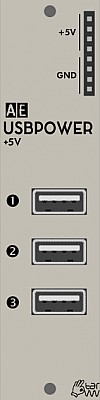
USBPOWER
This module provides 3 standard USB connections for powering external equipment. Take care not to draw more power than your AE Modular power supply offers. Check the milliampere (mA) value on the power supply and your attached devices.
Inputs
None.
Outputs
- 3 x USB connections - power supply only.
- 4 x +5V - +5 volt output
- 4 x Ground - earth for completing circuit for DIY modules etc.in conjunction with +5 volt output.
Controls
None.
Patch Suggestions
The +5 volt out can be used as a modulation source, although other modules provide a constant voltage as well. Use a 4ATTMIX or 2ATTCV to attenuate as needed.
This module comes with a USB light so mount the module so it shines down over your patching/playing area, or at least not into your eyes....

µSH-RNDM-NOISE
This 1/3 height micro module is jam packed with features such as:
- 2 channel Track or Sample & Hold
- Noise
- Random clock
This module needs to be installed on the µBASE module!
Module power consumption: ? mA
Inputs
- IN 1 - the audio to be "sampled" on channel 1.
- TRG 1 - when activated the module takes a voltage measurement from input 1.
- IN 2 - the audio to be "sampled" on channel 2.
- TRG 2/CLK - when activated the module takes a voltage measurement from input 2 and can also act as clock for the random CV output.
Outputs
- 1 - S&H output channel 1
- 2 - S&H output channel 2
- R - Noise
- CLK - Random Clock
Controls
-
T&H / S&H Switch - changes the behaviour of either sampling the input and holding that voltage at the trigger point, or tracking the input when the trigger is positive; these cause very different CVs to be produced by the module from the same input.
-
TAP / MODE Button - tapping the button a few times sets the speed of the random value changes.
Tapping the button only one time: The random value output is updated when the input TRIG2 gets a trigger signal / it's synced to TRIG2 input.
Mode display and changing:
Holding the button displays the currently set mode:
1x: (audio) noise output
2x: random CV
3x: random CV, smoothed
To change the mode: Hold the button longer until the desired mode (= number of LED flashes) is displayed, then release the button. The mode and selected speed is saved when powered off.
Patch Suggestions
This module is very similar to the combination of NOISE and SAMPLEHOLD and all the patch suggestions for those modules apply here as well.
Track and hold is a very unusual function to be offered even in modular world, it can be a very interesting source of CVs; it can also be used to generate a semi-repetitive CV depending on the input.

µSUBOCTAVE
This 1/3 height micro module creates 2 outputs of square waves, one and two octaves below the incoming signal. It also produces another output 2 octaves below the incoming signal with a Pulse wave. There is also a mix output where the levels of the additional sounds can be controlled and combined with the original signal.
This module needs to be installed on the µBASE module!
Module power consumption: ? mA
Inputs
- IN - The incoming audio signal.
Outputs
- MIX - The mix of the original signal plus the one and two octave sub octave signals. Using the knobs you can adjust the level of each of the suboctave signals in the mix.
- -1 SQR - The full level output of the one octave square wave signal
- -2 SQR - The full level output of the two octave square wave signal
- -2 SQR - The full level output of the two octave pulse wave signal
Controls
- -1 OCT. - adjusts the level of the one octave signal in the mix.
- -2 OCT. - adjusts the level of the two octave signal in the mix.
Patch Suggestions

µTONE
This 1/3 height micro module provides a two channel EQ which allows you to control the higher and lower frequency of the incoming signal. It is essentially one channel of the 2TONE module.
This module needs to be installed on the µBASE module!
Module power consumption: ? mA
Inputs
- IN - the incoming audio signal
Outputs
- OUT - the output signal after the frequencies have been adjusted.
Controls
- LOW - Controls the amount of low frequencies in the output signal
- HIGH - Controls the amount of high frequencies in the output signal
Patch Suggestions
This can be used as a simple EQ for your output signal, eg. in performances where you want to "fade" out the whole track by removing the low frequencies.
The uTone can be made to self oscillate, a bit like a filter; the resultant sound can be processed through the rest of the AE like normal, filters and the Phaser module are recomended.
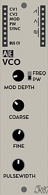
VCO
The voltage-controlled oscillator (VCO) is a typical analog audio oscillator with 1V/Oct pitch tracking for musical purposes. VCOs are one of the most basic audio sources in a synthesizer. Their sound is usually further shaped and refined by filters, wavefolders, voltage-controlled amplifiers (VCAs) and other audio effects.
Module power consumption: 16 mA
Inputs
- CV1 - control voltage input for pitch frequency (1V/Oct)
- CV2 - another control voltage input for pitch frequency (1V/Oct)
- MOD - control voltage input for modulating either frequency or the square wave's pulse width
- PW - dedicated pulse width modulation control voltage input
- SYNC - resets the waveform when a trigger signal is received
Outputs
- 2x RAMP - ramp/sawtooth wave output
- 2x TRI - triangle wave output, quieter than the other outputs so it might need amplification via the 2SIGNALAMP module for example
- 2x SQUARE - square wave output
- BUS CV - pitch control voltage form the MASTER I/O module's MIDI-CV converter
Controls
- MOD DEPTH Potentiometer - attenuator for the MOD input control voltage
- MOD DEPTH Switch - switches the MOD control voltage target between frequency and pulse width
- COARSE - coarse tuning of the VCO frequency
- FINE - fine tuning of the VCO frequency
- PULSEWIDTH - manual control over the square wave's pulse width, control voltage modulation is added to this potentiometer setting
Patch Suggestions
This video by Synths & Things explains the ins and outs of this module really well: https://youtu.be/vBKg-7lSAus
This video by The Tuesday Night Machines demonstrates frequency modulation sounds: https://www.youtube.com/watch?v=jVtANkhEBGY

VMBRIDGE
The VMBRIDGE module offers all necessary level adaptations for cross-patching between the Korg Volca Modular and AE modular! Although both use the same patching system, the signal levels are different and some combinations can cause distortions/clippings or even might harm each other
The module offers two audio and two CV connections for each direction (from/to Volca modular), plus two minijack connections for the CV and Sync in/out connections of the Volca modular.
Module power consumption: 3 mA
Inputs and Outputs
The module is designed as a mediator between modules on the AE modular and modules on the Volca Modular to make it safe to patch between the two devices. For this purpose there are two main sections on the module:
-
From AE to Volca - this is the top section with an arrow pointing to the right. The top left patch points labelled AU1 and AU2 take an audio signal from an AE module and translate it to the correct voltage for the Volca. You can then patch a cable from the corresponding patch point on the top right to the Volca. The same works for the patch points CV1 and CV2 but this works for CV modulation signals.
-
From Volca to AE - this is the lower section with an arrow pointing to the left and works the same as the above but in reverse. For audio signals patch the output of an oscillator (SOURCE) or LPG to one of the top right patch points in this section and then connect a wire from AU1 or AU2 to a filter or effect on the AE. Same applies for CV from the Volca for instance coming from one of the function generators.
3.5mm Mini Jacks at the Bottom of the Module
- CV TO VOLCA - sends CV pitch and gate to the Volca .Connect a stereo cable here to the CV-IN port on the Volca Modular. This connects the 1V/Oct to the top (GATE) output on the Volca patch port and the CV to the bottom (PITCH) output on the patch port on the Volca.
- SYNC I/O - carries a clock signal either from or to the Volca. Connect either a stereo or mono cable from here to either the SYNC-IN or SYNC-OUT port on the Volca Modular. Depending which jack you chose on the Volca, then the SYNC I/O patch point just above the jack becomes either an input or output.
All of this is explained in great detail in this tutorial video by The 5th Volt: https://youtu.be/YU4nTFdMy10
Patch Suggestions
Here is a techno jam:
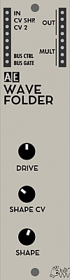
WAVEFOLDER
Basically, the WAVEFOLDER clips and folds an incoming waveform. Usually waveforms with little overtones like triangle or sine waves are used as input. In general, by the clipping and folding, the WAVEFOLDER enriches the input signal with more overtones.
The module is based on a design also used by Ken Stone for his CGS modular. The original circuit dates back to a publication from 1973.
Module power consumption: 3 mA
Inputs
- IN - Audio or CV signal input
- CV SHP. - Wave folding CV control through the SHAPE CV attenuator
- CV 2 - Wave folding CV control without attenuation
- BUS CTRL - MIDI CC20 CV from the MASTER I/O bus
- BUS GATE - MIDI Gate CV from the MASTER I/O bus
Outputs
- OUT - Processed input signal
Controls
- DRIVE - Amplifies the input signal
- SHAPE CV - Folds the top of the input signal waveform down, if the amplification is strong enough. Folding increases by turning the pot clockwise.
- SHAPE - Clips the input signal waveform hard from the top all the way down to silence. Clipping effect increases by turning the pot counterclockwise.
A tutorial video by The Tuesday Night Machines:
Patch Suggestions
The Wavefolder can be used to boost any signal level, e.g. Triangle wave on the VCO.
Create a dull sine wave to process with the WAVEFOLDER: Run a square wave VCO through a low pass filter with a low cutoff frequency. For pitch sequencing, you might want to add a little bit of pitch CV to the filter cutoff control too, not just the VCO. This is often called “keyboard tracking” in non-modular synths’ filter settings, which makes sure that the filter opens up a little on higher notes. Otherwise, a constant cutoff will dull the sound of higher notes more than lower notes.
WAVEFOLDER Feedback: Patch the input signal (e.g. a triangle wave) in a mixer and the mixer output into the WAVEFOLDER. Then patch one WAVEFOLDER output back into another mixer input and slowly turn the mix knob up. For voltage control over the feedback, patch the WAVEFOLDER output in a VCA and from there into the mixer. Modulate the VCA with an LFO, Envelope, Sample & Hold or Sequencer then. Feedback can get very crazy quickly, so start with low knob and modulation settings.
Since the WAVEFOLDER creates complex (harsh sounding) waveforms, you can send them through a filter to smooth them. As they are different than your standard square or sawtooth waves, they also sound different, and often more interesting, through filters.
Try modulating the WAVEFOLDER’s shape with its input signal, i.e. send the triangle or sine wave audio signal in the audio input and also in the SHAPE CV input.
This video by TTMs gives an excellent demo of what the Wavefolder can do:-
Sound Examples
WAVEFOLDER-focused jam session with patch notes: https://www.youtube.com/watch?v=9BOl5g6HDqg
Jam session in which the main mix is sent through the WAVEFOLDER: https://www.youtube.com/watch?v=sALZ7ZcWhRY
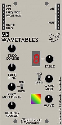
WAVETABLES
The WAVETABLES module is a sound module based on the wavetable technology first heard on the PPG range of synthesisers. It has been developed in close collaboration with Paula Maddox from DOVE Audio who is also the designer of such classic synths as the Modal 002, Modal 001 and Modal 008 from Modal Electronics.
There are 7 different tables each with their own unique sound, from very gentle, though vocal sounds, into rich bell like tones to harsh digital tones. Each table has a number of waveforms that can be morphed into each other as you scan through them with either a potentiometer or CV control.
Module power consumption: 40 mA
Inputs
- CV1 - base pitch of the oscillator
- CV2 - base pitch of the oscillator (added to the first)
- FM - Modulating the pitch
- WAVE - modulate the wave position within a table
Outputs
- Out - output of the wavetable sound
Controls
- Coarse Frequency - Coarse selection of base frequency
- Fine Frequency - Fine control of base frequency
- FM Depth - Amount the incoming FM CV will change the pitch
- FM Bipolar - When on, the FM CV will be centered around the base frequency, so an incoming triangle wave will modulate the pitch both up and down, in the off position the incoming CV will only module the pitch up.
- Detune - Adds a second version of the same waveform, creating anything from a subtle chorusing type effect to a full octave above.
- Table - Selects the current table that you are working with
- Wave Mod - sets the amount of the incoming CV that affects the wave you hear
- Wave Bipolar - When on the wave CV will be centered around the chosen wave, so an incoming triangle will move both up and down through the table. In the off position the incoming CV will only move up through the table.
- Wave - Selects the waveform from within that table
Patch Suggestions
The output of this module obviously can be run through the rest of the AE system, a hybrid digital/analogue synth at a very good price! The Nyle filter with its CV adjustable resonance is recommended...
The CV control of the wavetable position is an amazing tool; using an envelope you can get subtle or bonkers effects that change as you hold a key down.
In a similar vein, using an LFO square wave and the wave mod knob, you can set the wavetable position so it alternates between 2 waveforms. An attuenator, (e.g. 2CVTOOL can be helpful here.
If you want something a bit more experimental, you can use a Sample-and-Hold to randomly select the waveform, and if you put that through the SLEW LIMITER first you can control how smoothly it jumps between waveforms.
Demo
Thanks to Felix from The Tuesday Night Machines for this excellent demo video:
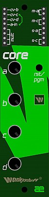
Core1.ae
This is a programmable sound generator from Wonkystuff. The Core series are small, reprogrammable devices, based around a particularly limited microprocessor (as used by Bastl in their Kastle) having a mere 8kB of code space and 512 bytes of RAM! We find that with these limitations, some interesting algorithms can still be programmed and new and interesting sound generators and modulators can be constructed.
It comes with dr1 firmware already loaded to be a complex oscillator. However you can find and download many other firmwares directly from this page:
https://wonkystuff.net/tag/examplecore/
Module power consumption: 25mA
Inputs
- cv-b - CV control for the b parameter
- cv-c - CV control for the c parameter
- cv-d - CV control for the d parameter
- a-in - Audio input for effects and also to upload new firmware
Outputs
- m-a - PWM produced output which is AC coupled (for audio signals)
- m-c - PWM produced output which is DC coupled (for control signals)
- s-a - digital output which is AC coupled (for audio signals)
- s-c - digital output which is DC coupled (for control signals)
Controls
- a potentiometer - control for parameter a
- b potentiometer - control for parameter b
- c potentiometer - control for parameter c
- d potentiometer - control for parameter d
- rst button - used for uploading new firmwares, see below for instructions.
- led - this LED can be programmed to flash. It also indicates the upload progress when uploading a new firmware.
Controls of the default dr1 firmware
The core1.ae module comes with the dr1 firmware pre-installed. This is a complex oscillator which is really fun to play with and also gives you a selection of different waveforms.
Outputs
- m-a/c - Main audio output
- s-a/c - Square-wave sub-oscillator output
Controls
- Knob a - 'perturbation' (random switching of wavetables
- Knob b - wavetable select (Sine, Triangle, Square, Saw with intermediate positions being a blend)
- Knob c - Main oscillator frequency (Fundamental pitch)
- Knob d - Secondary oscillator frequency (enveloped by the main oscillator)
Inputs
As per the normal operation of the core1.ae the inputs for b, c, d can be used to CV control the parameters which are otherwise controlled by the corresponding knobs. The knob position provides an offset to which the input CV is added.
How to program the Core1.ae module
This is very old school in that you load new programs in to the module via the audio input. This page describes everything you need to know:
https://wonkystuff.github.io/arduino/
Some very easy to follow examples are available in this Github repository:
https://github.com/wonkystuff/coreExamples
There is a section on the AE Modular forum to discuss programming this module:
Kaestle
This is Wonkystuff’s take on the Bastl Instruments reknown Kastle minisynth, re-engineered to fit the AE modular format. Although set up as as a 2 operator FM synth, It offers several sorts of synthesis within its confines.
Inputs
The WS Kaestle's inputs are located mostly on the left hand side of the module. They are 4 sets of 3 by each knob those inputs affect, a group of 4 on the lower right, and the top 2 of the other square of sockets.
- OSC Pitch - row 3 sockets top left - These are 3 CV inputs that work with the 2 OSC Pitch controls as covered below.
- OSC Timbre - row 3 sockets, 2nd row down, left hand side - These are 3 CV inputs that work with the 2 OSC Timbre controls as covered below.
- Waveshape - row 3 sockets, 3rd row down, left hand side - These are 3 CV inputs that work with the 2 Waveshape Knobs as covered below.
- LFO RATE - row 3 sockets bottom left - These are 3 CV inputs that work with the 2 LFO Rate knobs as covered below.
- Mode - top 2 sockets of square on right near the 2nd Osc Timbre knob - These inputs change the way the module behaves:-
- Nothing patched, the Main Osc out is phase modulation, the Secondary is phase distortion. Both are digital synthesis methods, the first by Yamaha, the 2nd by Casio.
- A low signal (usually the - outout) is attached, both outputs produce white noise, the secondary with more "character".
- A high signal (e.g. th + output) is attached, the main Osc output is track & hold modulation, the secondary is formant synthesis. The latter is useful for emulating a voice or animal sounds.
- Bit In - Top 2 of 4 sockets square in lower right corner - These inputs set the function of the Stepped outputs.
- Nothing patched, the output generates 16 pulses per LFO cycle.
- A low signal (usually the - outout) is attached, the output generates 8 pulses per LFO cycle.
- A high signal (e.g. th + output) is attached, the pulse output is random.
- LFO RST - Bottom 2 of 4 sockets square in lower right corner - This resets the LFO to the high point of the triangle waveform. This means any modulation will be at its maximum and then descend. Also useful for syncing the LFO with your main clock pulse etc.
Outputs
The WS Kaestle's outputs are not all located in the usual, top right hand side of the module. They are all marked by having a white outline around them.
Group 6 sockets top right:-
- OUT - Main Oscillator out.
- -n - Secondary Main Oscillator out - this will produce different sounds than the main out
The common AE "trick" of patching an output into another to mix them works well with the Kaestle.
Bottom 2 of 4 socket square below:-
- - - A ground (0V) "signal".
- + - A set +4V signal.
Square of 9 sockets right side of module, all are from the LFO:-
- Stepped - top row of 3 - This produces a number of pulse per cycle of the LFO wavform, controlled by the mode input.
- Triangle - middle row of 3 sockets - the main LFO output. For modulation etc.
- -n - Bottom row of 3 - the pulse wave output of the LFO, good for triggers etc.
Controls
There are 2 knobs for each parameter; left and right. The Left knob controls the amount of modulation etc from the relevant input(s)
The parameter value associated with the label, (Pitch/Timbre/Waveshape/LFO Rate), consists of the position of the knob in the centre of the panel PLUS the signal from the inputs, whose level is controlled by the left hand knob.
- OSC Pitch - controls the main frequency of the sound.
- OSC Timbre - This is techinically mislabelled (like the original) in that it controls the pitch of a 2nd oscillator; what this oscillator does however, is "react" with the main one to create phase addition/cancellation, distortion and all sorts of other good stuff so is quite correct musically!
- Waveshape - This has two functions; the simple one is that it sets the pulse width of the -n out. The main purpose is to add/remove harmonics by changing the waveform of the main oscillator. This can vary from subtle to manic....
- LFO RATE - controls the speed of the Low Frequency Oscillator, which is great for varying vibrato, (pitch modulation), and many other parameters to make the sound more interesting, even bonkers!
Display
The LED shows the clock or tempo of the LFO
Patch Suggestions
This is a deceptively powerful module, you may find the original's user manual helpful, and has a useful tips and tricks section as well. There is also a brief explnation of the various synthesis types available on this module, basically it is a must read!
https://bastl-instruments.com/content/files/manual-kastle-v1.5.pdf
There is also an excellent video by RSKT:-
Until this module, the only way to have CV control of an LFO was to use a regular oscillator and use a divider module to lower the resulting frequency. This module makes that patch a lot easier! Changing the frequency of the LFO using an Envelope is superb for making even basic sounds more interesting. Having a slower LFO, (or Kurt's Sloth), control the frequency is excellent for subtle variations in sound, very nice on filter cutoff for instance.
Kaestle Drum
This is Wonkystuff's take on the Bastl Instruments Kastle Drum, re-engineered to fit the AE modular format.
Inputs
The WS Kaestledrum's inputs are located mostly on the left hand side of the module. They are 4 sets of 3 sockets by each knob those inputs affect, a group of 4 on the lower right, and the top 2 of the other square of sockets.
- Drum - row 3 sockets top left - These 3 inputs work in conjunction with the 2 Drum knobs as covered below. A signal above 3V here will trigger the drum synth.
- Pitch - row 3 sockets, 2nd row down, left hand side - These 3 inputs work with the 2 Pitch controls as covered below. A signal above 3V here will trigger the Noise output.
- Decay - row 3 sockets, 3rd row down, left hand side - These 3 inputs work with the 2 Decay knobs as covered below.
- Tempo - row 3 sockets bottom left - These 3 inputs work with the 2 Tempo controls as covered below.
- Trig In - top 2 sockets of square on right near the 2nd Pitch knob - The main envelope trigger for the drum synth and Noise output. These inputs are dynamic, i.e. a 0.5 to 2V pulse will trigger a quiet envelope. A 2-3.5V pulse will trigger a louder envelope and a 3.5 to 5V pulse will trigger the loudest envelope. These voltages are approximate. If you have 2 signals going into the inputs it is really easy to add accents/variation to your drum/noise sound. Excellent for Hi-hats....
- Feed - Top 2 of 4 sockets square in lower right corner - This input controls the Pattern output of the LFO as shown below.
- CLK IN - Bottom 2 of 4 sockets square in lower right corner - A trigger pulse here resets the LFO to the highest point of the triangle wave so you can, in effect, create different LFO waveshapes. This also means any modulation the LFO is doing will be at the highest level and descend.
Outputs
The WS Kaestledrum's outputs are not all located in the usual, top right hand side of the module. They are all marked by having a white outline around them.
Group 6 sockets top right:-
- Drums (3) - Main output of drum synth.
- Noises (3) - noise/glitchy noise output, independent of the drum synth.
The common AE trick of putting one output into the other to mix them together works well on the Kaestle Drum.
Bottom 2 of 4 socket square below:-
- - - a ground (0V).
- + - a steady +4V which can be used to add to other CVs etc.
Square of 9 sockets right side of module, all are from the LFO:-
- Pattern - top row of 3 - These outputs generate 4, 8 or 16 pulses depending on the CV at the Feed input. If nothing is attached to the Feed input you get 8 pulses per LFO cycle. If a low signal/ground (e.g. -) is connected you get 4 pulses per LFO cycle. If a high signal (e.g. +) is connected you will get 16 pulses per LFO cycle. Switching between patterns will cause psudo-random pulses during the cross over.
- LFO - middle row of 3 sockets - The regular LFO output, this is a triangle wave but it is variable by use of modulation (particularly Tempo or CLK In).
- CLK - Bottom row of 3 - Pulse output of the LFO, for triggers etc.
Controls
There are 2 knobs for each parameter; left and right. The left knob controls the signal level from the relevant input(s).
The parameter value associated with the label, (Drum/Pitch/Decay/Tempo), consists of the position of the knob in the centre of the panel PLUS the signal from the inputs, whose level is set by the left side control.
- DRUM - There are 8 drum sounds in the Kaestle Drum, and this knob is how to move between them. Moving to another sound's "zone" triggers that sound. Thus, if you have a square wave CV you can switch between 2 sounds triggering them each time, a constant rising/falling CV could trigger all 8 sounds....
- Pitch - Sets the frequency/pitch of the selected drum sound(s).
- Decay - Sets the length of time the module will sound with each trigger. Note the centre (vertical) position is for the shortest envelope, and turn clockwise to get longer decay. Turning the knob anti-clockwise from the centre also increases the decay time, but also affects the pitch.
- Tempo - Sets the apparent speed of the rhythmic pattern. Thus subtle variations in tempo (or not subtle!) can be controlled with a CV and the left knob in this section. An external envelope can be quite fun....
Patch Suggestions
If you find this module a bit mind blowing at first, you may find the original's user manual helpful. Most of the detail on this page came from this source.
https://bastl-instruments.com/content/files/manual-kastle-drum-web.pdf
There is also an excellent video by RSKT:-
This module screams more than most to be patched with the rest of the AE; an external envelope on the tempo has been mentioned, the trigger could be manual, the Kaestle Drum's LFO or anything else. Use of LFOs to vary the sound can bring great rewards for instance, the attenuator Knobs on the left side of the module being really useful here. Very easy to descend into chaos however, 
If Wonkystuff ever upgrade the firmware, or provide different programming for the module, you will be able to find it on https://github.com/wonkystuff/kastle
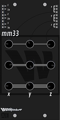
mm33
The MM33 Mk2 is now available, ready built:-
https://wonkystuff.net/product/mm33-matrix-mixer-for-ae-modular-v2/
This is a standard buffered matrix mixer where each output contains a mix of signals 1-3 determined by the position of the controls. Controls are laid out such that inputs are arranged in rows (number of stripes indicates the input number), and outputs are arranged in columns.
This is an introduction and build video of the mm33
The outputs are buffered and have a small amount of gain. Each output has multiple output pins.
Module power consumption: <1 mA
Inputs
Version 1
- 1 - CV input for channel 1
- 1a - Audio input for Channel 1
- 2 - CV input for channel 1
- 2a - Audio input for Channel 1
- 3 - CV input for channel 3
- 3a - Audio input for Channel 3
Version 2 has improved inputs so the same input can be used for CV or audio, this is optimised for the outputs via a switch instead (see below). V2 also has a
- MULT - passive mixer/splitter not connected to the module circuit.
Outputs
- x (x3) - The combined signal whose level(s) are set by the left hand column of knobs.
- y (x3) - The combined signal whose level(s) are set by the central column of knobs.
- z (x2) - The combined signal whose level(s) are set by the right hand column of knobs.
Controls
- The top row of knobs (1 line) is for channel 1, the left knob sets the level for output X, the middle knob sets the level for output Y and the right knob the level for output Z.
- The middle row of knobs (2 lines) does the same for input 2.
- The bottom row of knobs (3 lines) does the same for input 3.
Version 2 also has 3 switches, 1 for each output to select between audio and CV signals. The difference is audio in the AE is centred around 2.5Vs, whereas CVs are 0 to 5V.
Patch Suggestions
This mixer is excellent for combining CVs and sending to multiple outs, a veritable modulation matrix!
It can be very useful to use as a submixer to combine oscillators/waveforms before sending to different filters or other processing on different outputs.
If you need CV control of a level, you can do this by adding a VCA before the input but this will obviously affect all 3 outputs for that signal. Conversely you can put a VCA on an output before going on to further processing but this will affect any input signals sent to that output. If you have a spare input or output, this can be used with a VCA to give you CV control of a lone signal selected by the relevant knob being turned up....
It can be used as a straight forward, 3 Channel attenuator by each input going to a different output, make sure the knobs for the other outputs are turned down!
Matrix mixers are great tools for all kinds of experimental music and are especially useful for no-input mixing type of projects. Here is a Youtube video of a similar mixer and how to use to make music:
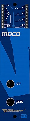
Moco
The concept behind the morph controller is that a series of 4 overlapping triangular envelopes are generated from an input CV (plus manual offset), meaning that it can be used with a quad vca (such as the qvca) to fade across four audio sources. As it was originally thought of as a companion to the qvca, the moco also has a simple 4:1 audio mixer for recombining the four outputs, saving the use of a separate mixer module.
Module power consumption: 20mA
Inputs
- CV - This takes a zero to 5V signal and sets the "mix" of the outputs accordingly, in the same manner as the POS knob, please see below.
- Mixer in - the next 4 sockets down the left hand side, marked going to a triangle pointing right with a plus sign in it. To save needing external VCAs in certain applications &/or for use with CVs from other modules, these 4 inputs are combined to a signal issued at:-
- MIX (x3) - Outputs from the combination of whatever is plugged into the 4 sockets above.
Outputs
When an output is not active, it's level is 0V. The maximum voltage is around 4.5V when it is that output being active on its own.
- A (x2) - In normal usage, this is first CV to be activated, (lowest CV input voltage), but it depends on the CV and/or Position knobs. It overlaps with output B
- B (x2) - This CV overlaps with A and C
- C (x2) - This CV overlaps with B and D
- D (x2) - This is the last CV to be activated, (highest CV input voltage); it overlaps with C
The markings to left of the outputs give a graphic representation of this delay/pattern.
Controls
- CV - this is an attenuator for the CV input so you can set the amount of morphing/sweep between the outputs.
- POS - This gives manual control of the morphing/"mix" from just output A, A&B, B only, B&C, C only, C&D, D only.
Patch Suggestions
This module is based on the Doepfer A-144 (now discontinued) whose page can be found here. This page has a users manual in English or German which is very detailed and useful.
Wonkystuff have an excellent introductory video to this module:-
Though the video demonstrates the CV input with an LFO, the use of an envelope to mix your audio signals can mean you can have some superb sonic changes consistently on each key press/activation, not necessarily needing a filter... For this, the Tangible Waves 4VCA module is excellent due to having the mix outputs.
As almost demonstrated in the video, you can produce a 2, 3 or 4 step beat/pulse with this module and an LFO. This is shown is mixing VCOs but these CVs could go to "mix" other sounds, raise a filter cutoff, go to an envelope module (ADSR could be interesting) and anywhere else you can think of to send a CV...
For randomness, try the Wonkystuff rbss as the CV in, or could use sample and hold.
qvca
This is quad VCA which is designed only for audio use (unlike the standard Tangible Waves 2VCA which can be applied to both audio and CV signals).
https://wonkystuff.net/product/qvca/ The original production run of red fronted modules.
https://wonkystuff.net/product/qvca-black/ The current model with a black front panel. Functionally they are the same.
Inputs
- CV 1-4 - accepts an incoming control voltage, 0 volts is no signal to the output(s), +5V is the loudest signal.
- VCA 1-4 - accepts the CV or audio signal you want to control
Outputs
- CV 1-4 - the CV is inverted (i.e "rotated" around 2.5V); if input is 0, the output will be 5V. If the input is 3.5V the output will be 1.5V
- VCA 1-4 - Individual outputs of the 4 channels, the level set by the relevant CV input.
Controls
- There are none!
Patch Suggestions
This is a good module to do stereo with, as the panning can be CV controlled. Send to the CV output of the left or right channel to the CV input of the channel doing the other side.
This feature can also be used to produce "Ducking". This is when a sound is reduced/removed when another sound plays. This is most often seen in radio/TV broadcasts when the announcer starts to speak the music will quieten. Like most effects it can be subtle or blatant. Send the CV output of the sound you want to play to the CV input of the sound you want to quieten/silence. Fiddle with the levels/CVs to get the effect you want. In some cases you may need an attenuator/mixer or a module like the 2CVTOOL
The 5th Volt has a video about this module

RBSS
The rbss (random bit-shift sequencer) module is inspired by the famous "Turing Machine" Eurorack module by Music Thing Modular which in turn was inspired by many previous shift-register sequence generators.
When it is in stock, you can buy this module at Wonkystuff.
NOTE: if you have an older rbss module of serial number lower than 130, then you might have issues using it with the QUANTIZER module from tangible waves. This is due to some noise that is output by the module which the digital QUANTIZER module can't quite process. If you have this problem, then you can easily fix this yourself if you know how to use a soldering iron. Please follow the instructions on this page: https://wonkystuff.net/rbss-quantizer-issue/
Inputs
- clk in - Every time there is a rising edge on the voltage in this input, the sequence shifts one step. This can be driven up to audio rates for some interesting noises!
- len cv - The control voltage on this input is added to the control voltage from the front panel length control (so if the knob is fully clockwise, this voltage will have no effect)
- chance cv - The control voltage on this input is added to the control voltage from the front panel chance control (so if the knob is fully clockwise, this voltage will have no effect)
- bus clk - MIDI clock signal, via the master module.
Outputs
- a out (x3) - an audio-coupled output which will generate a pulse proportional to the difference in voltage between adjacent sequence steps;
- cv out (x3) - a control voltage representing the current bit-shifted binary pattern;
- clk out - a simple square clock signal
Controls
- rate - This changes the frequency of the clock pulse appearing at the clk out pin. (In order to trigger the rbss, the clk out must be connected to the clk in).
- chance - this specifies the probability that the next step in the sequence will change voltage, from 0 (never) to 1 (always).
- length - this is the number of steps that will be present in the sequence, from 1 to 16.
Patch Suggestions
You the clk out to trigger other modules, e.g. SEQ8 or TRIP modules).
This video shows how you can use the RBSS together with the SEQ16 to create long evolving sequences. https://youtu.be/lQotLnLqgHA
This video demonstrates how to use the audio output of the RBSS. https://youtu.be/apqzOGBofuc
Here is an ambient patch that uses 3x RBSS modules. https://youtu.be/T-sKgZNlKrM
µBD55
This 1/3 height micro module is a Bass Drum cloned from the Boss DR-55. Decay and Pitch have been incorporated for increased flexibility.
This module needs to be installed on the µBASE module!
µRS55
This 1/3 height micro module is a Rim shot circuit cloned from the Boss DR-55. Decay and Pitch have been incorporated for increased flexibility.
This module needs to be installed on the µBASE module!

XMIX
XMIX offers 4 mixers and 2 attenuators in a 1U package, ideal for small systems but also useful for larger systems where users are wanting attenuators, and to to combine CVs etc.
One 3 channel mixer has level controls, the others are passive mixers but two of the mixers can combine up to 8 signals (some with attenuation).
Module power consumption: 5 mA
Inputs
(Top left)
- A 1, 2, 3 - The 3 inputs for mixer A, their level can be individually controlled using the knobs below.
- B 1, 2, 3, 4 - The 4 inputs for mixer B, their level must be controlled earlier in the signal chain. The B mixer is meant for CVs only, and is ideal for that purpose.
(Center right)
- C In (x8) - the left side 4 inputs are full volume/level, the right side 4 inputs are 1/3 volume/level; other than this the respective levels must be controlled at the source.
- D In (x8) - the left side 4 inputs are full volume/level, the right side 4 inputs are 1/3 volume/level; other than this the respective levels must be controlled at the source.
( Bottom right) - Each column is the same, so there are 2 separate attentuators
- 1.00, 0.8, ... 0.05 (x7) - The inputs for the Attentuator from no effect (1.0) to almost silent/stopped (5% of the input volume/signal). The bottom socket is the output. Do try using more than one input at once...
Outputs
(Top right)
- OUT A (x2) - The combined signals from inputs A1, A2 and A3, their level controlled by the knobs below.
- OUT B (x2) - The combined signals from inputs B1 to B4 inclusive.
- OUT C (x2) - The combined signals from all the C inputs.
- OUT D (x2) - The combined signals from all the D inputs.
(Bottom right)
Each column is a separate attenuator, and are identical.
- Out - The output from any of the 7 inputs used in the column above, their level depending on which input(s) are used.
Controls
-
A1 (knob) - controls the level of input A1 in the A outputs.
-
A2 (knob) - controls the level of input A2 in the A outputs.
-
A3 (knob) - controls the level of input A3 in the A outputs.
-
Audio/DC (switch) - there are 3 of these, Mixer A's is at the bottom of the module, Mixers C & Ds' are in their respective sections. This switch optimises the circuit for use with either audio (rotates around 2.5V) or CVs (0-5 volts); this is generally to get the best audio quality but you may prefer the switch in the "wrong" position sometimes!
Patch Suggestions
You can use the 2 attenuators to help set the level(s) in the B, C & D mixers.
Mixers can be combined, e.g you may feed the C mixer out into one of the A mixer ins, in effect sub mixing.
There are no CV controls of signal level, but this can be done before or after mixing with a VCA and whatever you wish to use to control the level. The VCA control is only needed on the input(s) you wish to evolve/change from a CV control, e.g. allowing a burst of noise on a snare sound but let the tuned element(s) go on longer by a VCA after the mixer.
This module is useful for combining CVs, especially where you have a lot available like, for example, the JOYSTICK module.
The attenuators can be useful for releasing modules with level controls so they can be used for something that needs more precision or you wish to alter the level of attenuation as the sound plays. An example of this is LFO level control for most patches, (some modules have CV input level control); if you are not varying the LFO modulation amount then an attenuator should be able to do the job.

4VCA
The 4VCA has four separate Amplifier circuits within; all switchable DC/CV and audio, and a mix output. It is therefore also a 4-channel CV controllable mixer for audio or CV signals.
There is also a 2VCA module available, but this does not have the mix output..
Inputs
- IN 1-4 - accepts the CV or audio signal you want to control
- CV 1-4 - accepts an incoming control voltage, 0 volts is no signal to the output(s), +5V is the loudest signal.
Outputs
- Out 1-4 - Individual outputs of the 4 channels
- Mix - the mix of all channels
Controls
There are 4 switches that allow you to switch the channel voltage between audio and control voltage (DC). The difference is that there is some filtering of the signal when put into audio mode to prevent crackling or popping noises from voltage differences.
Patch Suggestions
By using 2 channels and an LFO you can have panning over stereo, the signal will need inverting for 1 side by, for example, the 2ATTCV module. The Mix output will still be mono....
This module is really handy for combining CVs to go to a module with one CV input. You may want an keyboard CV, envelope, LFO and a manual adjustment (e.g. Joystick) to the pitch CV of OSC 1 on the 2OSC/D module....
This module is also useful to have CV control over another CV, e.g. if you want to fade in an LFO providing vibrato to an oscillator using an envelope. This in combination with the previous patch suggestion is a really powerful modulation patching ability for the AE system.

6MUTE
This module allows you to mute up to a maximum of 6 independent channels via the press of a button. It will not put any clicks or noise in an audio signal.
Inputs
- IN 1 to IN 6 - accepts any CV or audio signal controlled by the relevant numbered button below.
Outputs
- Out 1 to Out 6 - No signal if the relevant numbered button is lit, signal from the same number input if not.
Controls
- 1 to 6 buttons - controls whether the signal at the same number input is allowed through to the same number output. E.g. Button 4 controls the signal from input 4 to output 4.
Patch Suggestions
The most obvious use is for dropping in and out separate parts of your AE audio in a live situation.
It can be excellent used in conjunction with a rhythm patch to drop a percussion sound in/out which can totally change the feel of the groove. This could be one sound from the Drum Kit Module, one from the Kick Module and sounds from the Algodrone Module amongst others
Muting any sort of CV signal can be useful; a good example is pitch modulation (vibrato) on/off. Another is an offset voltage which opens or closes the filter depending on the mute switch position. There are many, many others...
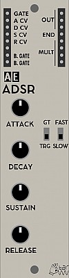
ADSR
The ADSR module offers the classic four-stage envelope (Attack, Decay, Sustain, Release) which accepts CV control over each of the stages. For the time values (A, D, R) the value set by the knob can be increased to five times the duration by the corresponding CV value. For the Sustain value the knob and CV value are simply added.
The envelope is also loop-able by patching the end output into the gate input, becoming a very adjustable LFO.
Module power consumption: 10 mA
Inputs
- GATE - gate or trigger for envelope
- A CV - accept CV for attack stage of envelope
- D CV - accept CV for decay stage of envelope
- S CV - accept CV for sustain stage of envelope (value from knob will be added!)
- R CV - accept CV for release stage of envelope
Outputs
- OUT - CV from envelope
- END - a trigger CV generated when the envelope has finished
- MULT - unbuffered multiple, unconnected from the module's circuitry
- B. GATE - Gate signal from MIDI via the Master module
Controls
- ATTACK Knob - change the attack time from 0 (percussive) to either 2 or 16 seconds depending on FAST/SLOW switch
- DECAY Knob - change the decay time from 0 to either 3 or 24 seconds depending on FAST/SLOW switch
- SUSTAIN Knob - change the decay time from 0 to either 3 or 24 seconds depending on FAST/SLOW switch
- RELEASE Knob - change the decay time from 0 to either 3 or 24 seconds depending on FAST/SLOW switch
- GT/TR Switch - switch between GATE or TRIGGER mode. When in GT mode the envelope will rise according to the ATTACK knob &/or the A CV value(s) and stay open on the sustain level until the gate closes. Then the envelope will lower according to the Release &/or R CV value(s). In gate mode, the envelope CV value is, in effect, set by the sustain knob &/or S CV level. When in TR mode the attack part of the envelope will play out until it reaches full level and then initiate release part.
- SLOW/FAST Switch - In slow mode the attack, decay and release times are longer than in fast mode.
- MAN TRIG Button - sends a trigger signal to start the envelope. Always acts like a trigger even when GT mode is active. (note: the picture above does not show the trigger button)
Patch Suggestions
Envelopes are one of the basic modulation sources in subtractive synthesis. They are usually used to modulate amplitude, pitch or a filter.
The CV control of the envelope is extremely useful for doing characteristics like shorter release for higher pitch notes, lowering the sustain volume on higher (or lower) pitch notes so the sound stays more even in the mix - you may need an inverter like on the 2CVTool.
If you are wanting to do tremolo (volume) on a sustained note then this module is ideal; put the control CV (e.g. LFO, Joystick or Midi CC20 via master module) into the sustain CV and away you go - you are likely to need an attenuator...
One fun thing to do is to have an LFO or S&H doing a slight variation (i.e. use an attenuator) to the decay &/or release CV, nice on most things and can be brilliant on a percussion sound.
The ADSR can also trigger itself when the output END is patched into the GATE input. Depending on the values of ATTACK and DECAY this can make it into a slow moving LFO (low frequency oscillator) or oscillator in audio range, with varied waveforms which can, of course, be modulated via CV on this module. This can be excellent.....
For more details, explained with the similar 2ENV please refer to: https://wiki.aemodular.com/pmwiki.php/AeManual/2ENV
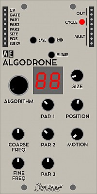
Algodrone
The ALGODRONE module is a sound and CV source based on the so-called bytebeat algorithms. These are simple formulas, usually expressed as one line of program code, that spit out a wide variety of interesting tonal to rhythmical patterns, regardless of their simplicity.
The ALGODRONE module contains a number of these algorithms plus three parameter knobs that change values within the current algorithm. These changes vary from subtle to dramatic, even with small changes, depending on the algorithm and the setting of the other parameters.
Some algorithms create sound loops, to use these more flexible the ALGODRONE can work in a kind of "granular" mode where a smaller part of the entire loop is repeated and with the POSITION knob you can move through the entire output loop.
Inputs
- CV - Base frequency for the algorithm
- GATE - Resets the current algorithm run to the start, this is useful for "one-shots"
- PAR1 - CV input for Parameter 1 of the algorithm
- PAR2 - CV input for Parameter 2 of the algorithm
- PAR3 - CV input for Parameter 3 of the algorithm
- GRAIN SIZE - CV input for Grain Size
- POS - CV input for position of the grain within the loop
Outputs
- BUS CV - (positioned on the left side) Pitch signal from the MIDI bus
- OUT - Output of the algorithm
- CYCLE - trigger output when a cyclic algorithm (loop) has reached its end before repeating
- MULT - unbuffered multiple
Controls
- ALGORITHM knob - selects the current algorithm, 67 factory and 30 user presets are available, the selected algorithm will be displayed in the small display to the right of this knob
- COARSE FREQ knob - coarse selection of base frequency. Although a higher frequency often leads to a higher pitched sound, each algorithm reacts differently to this and there can be drastic changes to the behaviour of the sound when the frequency changes.
- FINE FREQ knob - fine control of the base frequency
- PAR 1 knob - controls the value of parameter 1 of the selected algorithm. Each algorithm uses these parameters differently and not every algorithm uses all three or even any of the parameter. It is up to the user to explore how changes in parameters affect the sound.
- PAR 2 knob - value of parameter 2
- PAR 3 knob - value of parameter 3
Some of the algorithms produce sound loops which can be "frozen" and only a tiny fraction of the loop played at a time. This is called Granular Synthesis and the following three knobs control the "grain mode".
- GRAIN SIZE knob - only a tiny fraction of the complete sound loop the algorithm creates is played. The size knob controls how large the area is. When the knob is turned all the way to the left, then the grain encompasses the complete loop which means grain mode is OFF. Turning the knob gradually to the right increases the area of the grain, starting with a very short loop to a larger one.
- POSITION knob - when in grain mode this knob controls where in the complete sound loop the grain is playing. The position starts at the beginning of the loop with the knob all the way to the left and by turning the knob to the right the grain is shifted towards the end of the loop.
- MOTION - controls the way the grain plays within a frozen loop. Fully to the left, the grain played completely static. Turning to the right until the middle position, an increased triangle LFO modulation is applied to the grain position, adding some liveliness and smooth movement to the sound. When set to the right half of the knob (random) the grain is shifted randomly across the loop.
The ALGODRONE can also produce random algorithms which can be slightly mutated and then stored for later use. The three push buttons at the top are used for this.
- SAVE push button - store the current algorithm in a user location between 68 and 96. When the SAVE button is pressed, the numbers will flash and the ALGORITHM knob can be used to select the target slot number, the current algorithm in that slot will play. Once the desired slot has been found, press SAVE again to store the current random algorithm in that slot.
- RND push button - creates a completely new randomised algorithm
- MUTATE - when creating a random algorithm, this changes one item in the random algorithm, like the operator (e.g. "+" -> "*") or a constant value
Patch Suggestions
Bytebeat has been first explored by Viznut with a series of videos on YouTube and a very detailed analysis of the code on his blog: http://countercomplex.blogspot.com/2011/10/algorithmic-symphonies-from-one-line-of.html
When the Algodrone module was first announced there was quite a lively discussion on the AE Forum: http://forum.aemodular.com/thread/49/bytebeats-beginners-guide
This resulted in the very first beginners guide prepared by The Tuesday Night Machines which you can download here: http://nightmachines.tv/the-absolute-beginners-guide-to-coding-bytebeats.html
The Algodrone module does not really let you program your own algorithms, rather it contains a selection of 67 different built in algorithms with different uses of the parameter values and which react differently to the base frequency. Some are looping and can be used in granular mode, some aren't. Currently there is no list of what each algorithm does, so experimentation and patience is required to explore the sonic variety of each algorithm.
In addition to the builtin algorithms new ones can be "found" by repeatedly pressing the RND and MUTATE buttons which create random algorithms which can be saved into one of 30 user assignable slots (68 - 97).
Here is a very short video on how the Algodrone can sound like. https://youtu.be/-B2jgMYxYU8
Here is a video by Matt Wand (who has actually contributed a number of algorithms for this module) showing off the various ways in which this module can be used.
Overview video by The Tuesday Night Machines: https://youtu.be/Q6Mz9qpbUwo
This is a great exploration of the module's sonic landscapes by Max Richardson: https://youtu.be/eJLnuI2EC9U
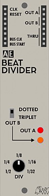
Beat Divider/ Midiclock Divider
This module is designed to break the 24 pulses per quarter note from Midi into more musically useful intervals for the modular synthesist. The Midi usually comes via the master module on the Bus CLK output on the module.
It can be used to divide other clocks, e.g. an LFO or even a VCO.
If you need more complex division, there is the Multi Mode Divider module:-
https://wiki.aemodular.com/pmwiki.php/AeManual/MM-DIV
Inputs
- Clock - the signal to be divided by this module.
- Reset - If things are not in sync, try triggering this input, e.g. with Midi Start signal from below.
The next 2 are actually outputs on the (usually input) left side of the AE module.
- Bus CLK - Midi clock via the Master module
- Bus Start - +5V trigger pulse when midi start is pressed on external equipment, via the Master module.
Outputs
- Out A (2) - main output of the module, set by controls below.
- Out B (2) - secondary output, set as dotted or triplet pattern of output A, i.e. a longer pulse per beat (dotted), or every other pulse being on the middle of the gap between the A pulses, (triplet) via switch below.
- Thru - Labelled Mult on older modules. A Passive mixer/splitter completely separate to the module circuits.
Controls
- Dotted/Triplet Switch - sets style of output B, as per above.
- Div knob - marked from 1/2 to 1/32, this set how many triggers you get per bar, 1/2 being the slowest and 1/32 the fastest and it varies in between so can be quite hard to sync to external sequences/drum patterns etc. until you get your ear tuned in. Use of the reset input helps with this.
Patch Suggestions
The most obvious use for this module is to sync the AE modular's sequencer modules, (e.g. SEQ16), but it can also be used to created general triggers or modulation in tempo with the midi clock.
Using an LFO as a clock it gives use several different triggers which can be really good for self playing modular improvisations.
If you use the A output as your Kick drum trigger, the B output can be really good for Snare or hi-hat type sounds.

BioT
A touch plate for the AE Modular. You can buy the DIY kit from either of these websites:
https://smallrocks.bandcamp.com/album/biot-touch-plate-demonstration-record
https://wonkystuff.net/product/biot-kit/
This is an excellent first kit if you are new to electronic construction/soldering. Very simple and a useful addition to your AE Modular, especially if you are performing live.
Wonkystuff has done a video about the building of the kit - https://www.youtube.com/watch?v=r4GuhFDfGpg
Each input/output pairing refers to the touch plate with the same symbol; usually you will do one connection to 2 (or more) different touch plates so your finger(s) make the electrical connection. Experiment!
Patch Suggestions
It is great to add a bit of variation to any modulation as you move/press your finger (or whatever else you fancy running over the touch plates!); can be nice on filter cut off too.
Also try with the audio signal directly through it, rather than as a CV control.
See also this video from Max Richardson as a demonstration...

BRAEDBOARD
The BRAEDBOARD module contains a breadboard area for solderless electronics prototyping so you can experiment with any kind of analog or digital electronics and make your first steps into electronics, starting with simple circuits for beginners to developing your own module.
It is supplied complete with some electronic components to get you started, these are listed on the Tangible Waves product page.
Inputs
There are no dedicated inputs at the top of the module. If your circuit needs input either from one or more of the onboard bus signals or from another module, you should patch it straight into the breadboard area.
Outputs (on the left hand side)
The left hand side offers convenient outputs to get access to the bus signals.
- Bus CV - a CV derived from the midi note number from attached device.
- Bus GATE - +5 volts when a key is pressed/held on attached midi device.
- Bus CTRL - a CV controlled by Midi CC20
- BUS CLK - the midi clock (if provided by attached device)
- BUS START - +5V pulse when start button is pressed on attached Midi device.
- BUS STOP - +5V pulse when stop button is pressed on attached Midi device.
- GND (2) - what it says!
Outputs (on the right hand side)
The outputs on the right hand side are "protected" by a 1k resistor so you can patch the output from your circuit into the resistor symbol and then take the "protected" signal from OUT1 or OUT2.
- OUT1 (2) – this is the one output picked up from the breadboard[s]
- Resistor-Symbol1 – connect the breadboard's output for OUT1 to the usual 1k output resistor here
- OUT2 (2) – this is another output picked up from the breadboard[s]
- Resistor-Symbol2 – connect the breadboard's output for OUT2 to the usual 1k output resistor here
- +5V (2) - what it says!
Upper / Red breadboard
The leftmost row of the breadboard is connected to +5V.
Lower / Black breadboard
The leftmost row of the breadboard is connected to ground.
Controls
There are no controls per default on this module, but it comes with a pre-soldered PCB with two potentiometers which you can incorporate into your circuit.
Patch Suggestions
Please see a (growing) number of projects in the DIY section of the Wiki.

CIRRUS
CIRRUS is a real-time granular processor for audio signals. This module is an adaption of Mutable Instruments' Clouds module, a well known module in the Eurorack world.
This module uses the extended firmware of the Eurorack Supercell module; meaning it offers four additional algorithms on top of the four original ones.
This module has been discontinued due to the Chip Shortage
Pitch Tracking Modes
The CIRRUS was sold with the original Superparasites firmware installed which was programmed for Eurorack hardware. There seemed to be some issue with pitch tracking with this version in conjunction with the AE Modular hardware and the adaption of the module/Firmware for this format. This lead to random pitch modulation of the grains which some people found undesirable.
Through extensive research and testing Mathias (aka @visuellemusik) has found the source of this behaviour and created 3 additional modes where this behaviour can be either switched off or controlled in creative ways. This new firmware also eliminates the need for calibration as described in the documentation for the original Superparasites firmware.
The new firmware is available as an audio file and can be easily uploaded to the CIRRUS via the audio IN port on the CIRRUS module.
You can find detailed instructions and the newest firmware file on the AE Modular Github here:
https://github.com/aemodular/superparasites/releases
The5thVolt has also created a video showing how to install the firmware and some sound tests for each of the modes. (There are now two additional sub modes which are not presented in this video, please refer to the instructions on Github how to access these)
Saving audio and presets
You can save up to 4 presets using the BANK button. These presets will persist even after the module has been powered down. The length of the saved audio depends on the current position of the TIME parameter (see below).
- To save the current audio buffer, press BANK for one second to begin the save process.
- Save into the current bank by pressing BANK again for one second.
- You can select a different bank to save into by tapping BANK briefly before saving.
- The save process will exit after saving is complete.
- The save process will be cancelled if nothing is saved within five seconds.
- The LED of the last-selected bank will blink ten times before saving is cancelled.
To load a saved preset:
- Tap the BANK switch to step through the four memory banks. Note that a brand new module (or a module that has just received a firmware upgrade) will have four empty banks.
- To reload the current preset bank without cycling through the other three banks first, press BANK while pressing TRIG at the same time.
Selecting the Audio quality
Pressing the TIME button quickly lets you cycle through the following modes for the length of the recorded samples. A longer sample time leads to reduced quality:
- 32khz, 16bit, stereo, 1 second (of audio buffer)
- 32khz, 16bit, mono, 2 seconds
- 16khz, 8bit µ-law, stereo, 4 seconds
- 16khz, 8bit µ-law, mono, 8 seconds
Note that Clouds’ 8-bit is a lovely flavour of 8-bit: µ-law compounding. It sounds like a Cassette, or a Fairlight - less hiss, more distortion.
Reverb
The post-processing reverb COMES after dry/wet MIX, so that it also affects the dry signal (so you can use Clouds as a simple reverb plus its main function)
Operating Modes
This module is very complex and each of the 8 algorithms changes how each knob and CV input behaves. Below is a comprehensive guide compiled by Matt Wand which explains all of this.
Downloads
You can also download the below guide as a PDF for printing and offline reading:
CIRRUS-manualBYmattwand.pdf
Another user of the forum (@sleeptotem) has created this cool cheat sheet:
CIRRUS CHEATSHEET.pdf
Clouds, Parasites, Super Parasites, SuperCell, Microcell.... and now... CIRRUS
ALL THE MODES: A COMPILATION & REWRITE/REEDIT OF ALL THE INFO OUT THERE FOR THE FIRMWARE CURRENTLY IN TANGIBLE WAVES ‘CIRRUS’ MODULE.
Word wrangled by Matt Wand (Rocky Smalls), all due credit to Emilie & all the additional firmware coders and documenters contributions sorted and compiled here.
In its tumultuous teenage years, Clouds tried to be everything, including a delay/pitch-shifter, a spectral processor, a projectionist and a cab driver in Rouen. as an adult cloud CIRRUS not only holds down those jobs but also indulges in Clairvoyance, Zeppelin Hangar management and Carbon neutral Rain Dancing!
HOW TO CHANGE THE MODE
Hold down TIME button for over 1 second the LEDs will flash, short press TIME button whilst flashing will move between modes thus:
(you can click on each link to jump straight to the mode description below)
- Mode 1 [●○○○]: Granular Clouds
- Mode 2 [○●○○]: Pitch Shift / Time Stretch
- Mode 3 [○○●○]: Looping Delay
- Mode 4 [○○○●]: Spectral Processor
- Mode 5 [○●●●]: Oliverb
- Mode 6 [●○●●]: Resonestor
- Mode 7 [●●○●]: Beat Repeat
- Mode 8 [●●●○]: Spectral Clouds
leave on desired mode for a second and it will settle in.
Mode 1: GRANULAR CLOUDS [●○○○]
Home sweet home. The Cumulous Nimbus original mode. Clouds continuously records the incoming audio into a short amount of sample memory. While recording time can reach up to 8s by reducing the audio quality setting, you ought to feel very guilty every time you think of this as “tape” - think of it as a space, a room. Using this recorded audio data, the module synthesizes a sonic texture by playing back short (overlapping) segments of audio (also known as “grains”) extracted from it.
Clouds allows you to control:
- From which part of the buffer the grains are taken.
- How long the grains are. At which speed/pitch the grains are replayed.
- How much overlap there is between the grains (density).
- Whether the distribution of grains in time is constant or random.
- Which envelope curve is applied to the grains - giving the impression of a “rough” or “smooth” texture. In addition, to create textures with a “blurry” feel, a diffuser (network of all-pass filters - like a reverb without tail) can be applied.
The module plays grains continuously, at a rate determined by the DENSITY and SIZE settings. A trigger input is also present, to explicitly instruct the module to start the playback of a new grain. The maximum number of concurrent grains is quite large - between 40 and 60. This specificity brings Clouds closer to the roots of granular synthesis, and allows the synthesis of varied textures even from basic waveforms - there’s indeed many more dimensions to granular synthesis than keeping a playback pointer moving through a SD-card sample!
It is possible, at any time, to HOLD (ie: Freeze) the audio buffer from which the grains are taken - In this case, the incoming audio is no longer recorded. Somehow, Clouds is the exact opposite of a sampler: by default, the module always samples the audio it receives, except when it is in the frozen state.
Front Panel Controls
- INPUT - gain from -18dB to +6dB. applies for ALL modes.
- HOLD - This latching button stops the recording of incoming audio. Granularization is now performed on the last few seconds of audio kept in memory in the module. long press HOLD will reverse playback of the buffer.
- POSITION - Selects from which part of the recording buffer the audio grains are played. Turn the knob clockwise to travel back(?)forward in time.
- SIZE - controls size of grains, Left = smallest, Right = largest
- PITCH - (transposition). At 12 o’clock, the buffer is played at its original frequency.
- DENSITY - generation rate & style of the grains. At 12 o’clock, no grains are generated. Turn clockwise and grains will be sown randomly, counter-clockwise and they will be played at a constant rate. The further you turn, the higher the overlap between grains. BEWARE THE DEADZONE! in this mode between aprox 10 o’clock & 2 o’clock no grains seem to be sown, possibly a Cirrus iteration problem, ie: that 12 o’clock area is TOO LARGE or TOO EXPONENTIAL maybe? but grains can be triggered via cv into the Trig input in this zone, so it has its uses.
- SHAPE - Morphs through various shapes of grain envelopes: square (boxcar), triangle, and then Hann window. Past 2 o’clock it activates a diffuser which smears transients.
- FEEDBACK - amount of signal sent back into pitch processing CAREFUL , adds decay to the buffer clearing when not HELD. at full can take nearly a minute to fade out if PITCH is near 12 o’clock.
- '''MIX dry/wet balance.
- PAN - Stereo spread of grains.
- REVERB - Amount and size of reverb applied to outgoing signal.
Inputs and Outputs
All CV inputs are calibrated for a range of +/- 5V (?? check with Robert) Voltages outside of this range are tolerated, but will be clamped.
- HOLD' gate input - When the input gate signal is high, stops the recording of incoming audio, just as latching the HOLD button would do.
- TRIGGER input - Generates a single grain. By moving the grain DENSITY to the 12 o’clock deadzone and sending a trigger to this input, Clouds can be controlled like a micro-sample player. An LFO or clock divider (or even a pressure plate) can thus be used to sow grains at the rate of your choice.
- Grain POSITION and SIZE CV inputs
- Grain transposition (PITCH) CV input with V/Oct response.
- MIX CV input - This CV input can control dry/wet balance,
- Stereo audio input - When no patch cable is inserted in the right channel input, this input will receive the signal from the left channel. ( check? )
- Grain DENSITY and SHAPE CV inputs
- Stereo audio output
There are a few things worth knowing about the settings
All settings are automatically saved, and will be restored the next time the module is powered on. Strange things happen when HOLD is enabled. Because feedback/layering can no longer occur in the recording buffer (hey, it’s frozen…), we route the output signal through delays and all-pass filters, and let the feedback build-up occur in this extra recording space - giving the sound a very reverb-like nature.
NOTE: the PAN knob, in most modes PAN is actually stereo “spread” you won’t hear any panning moving it left to right, counter clock wise: it will ‘mono-ize’ the output, turning clock wise: it will open up the stereo for the grains to appear randomly across the stereo field.
In the Mono quality modes in eg: Oliverb which is mono in only , PAN crossfades between the left and the right input. Remember that the left input is normalized into the right input, so with nothing patched in In L, this will have no effect. (check?)
Mode 2: PITCH-SHIFTER/TIME-STRETCHER [○●○○]
This mode is quite similar to the granular mode, except that it uses two overlapping grains synchronized with the most salient period of the sound. The grains are carefully spliced so that they mesh well with each other (a technique similar to the “deglitching” of early pitch-shifters).
Modulating POSITION when recording is HELD will “scrub” through the audio buffer. Clouds’ uses classic time-domain methods which are not suitable for polyphonic or percussive material (unless this percussive material is breakbeats and you liked Akai samplers.
Front Panel Controls
- HOLD - Loops the buffer, long press should reverse the audio held in the buffer?
- DENSITY - creates a granular diffusion effect based on all-pass filters.
- SHAPE - acts as a low-pass/high-pass filter.
- SIZE - controls the size of the overlapping windows used for pitch-shifting and time-stretching – from an extremely grainy “drilling” sound to smooth bits of loops.
- FEEDBACK - seems to be decay of the buffer ie: if not on HOLD CCW means when input muted buffer clears immediately, CW buffer runs out gradually ( 8 secs? )
- MIX - dry/wet balance.
- PAN - Stereo spread.
- REVERB - Amount and size of reverb applied to outgoing signal.
Inputs and Outputs
These work exactly like Mode 1: Granular Clouds.
Mode 3: LOOPING DELAY [○○●○]
The looping delay mode continuously plays back audio from the buffer without any kind of granularization.
Front Panel Controls
- HOLD - When HOLD is activated, the content of the audio buffer is looped (stutter effect).
- POSITION - controls the distance between the playback head and the recording head (in other words, the delay time). Modulating POSITION will create effects similar to vinyl scratching or manual manipulation of tape.
- POSITION - controls the loop start
- SIZE controls the loop duration.
- DENSITY - creates a granular diffusion effect based on all-pass filters.
- SHAPE - from 12 o’clock leftwards: low-pass filter, from 12 to the right: high-pass filter.
- FEEDBACK - adds decay to the buffer when not HELD. single bursts of input audio will decay like an echo/release envelope.
- MIX - dry/wet balance.
- PAN - Stereo spread of grains.
- REVERB - Amount and size of reverb applied to outgoing signal
Inputs and Outputs
Mostly like the modes before but:
- TRIG input/cv - When HOLD is enabled, sending a trigger on the TRIG input creates a clock-synchronized stuttering loop. Otherwise, the period of the trigger pulses sets the delay time – provided this delay is shorter than the recording buffer size.
Mode 4: SPECTRAL PROCESSOR[○○○●]
In this mode, the incoming signal is converted into “frames” of spectral data, that are stored, transformed, recombined, and resynthesized as a time-domain signal.
Front Panel Controls
- HOLD - freezes the audio buffer. see POSITION -
- POSITION - selects into which buffer the audio is poured (when HOLD is not active), or from which buffer the audio is synthesised (when HOLD is active). For example, set POSITION to its minimum value. Press HOLD. You get a first texture. Set POSITION to its maximum value. Release HOLD. Wait for something else to happen in the incoming audio. Press HOLD again. By moving POSITION you interpolate between the two textures which had been captured at the press of HOLD. Depending on the quality settings there are 2 to 7 buffers laid out over the course of the POSITION knob. What the module does is crossfade between a “wavetable” of FFT slices.
- SIZE - changes the coefficients of a polynomial that determines how frequencies are mapped between the analysis and synthesis buffers. It’s like a 1-knob GRM Warp. Over the course of the knob it’ll do spectral shifting, but also spectral reversal.
- PITCH - controls the transposition (pitch-shifting).
- DENSITY - determines how results from the analyzer are passed to the resynthesizer. Below 12 o’clock, there’s some increasing probability that a given FFT bin won’t get updated, causing a kind of partial freeze. After 12 o’clock, adjacent analysis frames are increasingly merged together (like a low-pass filter in the amplitude each frequency bin). At extreme settings, random phase modulation is applied to smooth things - giving you different flavours of spectral muddling/reverb.
- SHAPE - does two things: below 12 o’clock, it increasingly quantizes the amplitudes of the spectral components, like a very low-bitrate audio file. After 12 o’clock, it increasingly weakens the strongest partials and amplifies the weakest ones. This has the effect of making the spectrum more noise-like.
- FEEDBACK - sends signal back round through the pitch processor? (check?)
- MIX - dry/wet balance.
- PAN - Stereo spread of grains.
- REVERB - Amount and size of reverb applied to outgoing signal. Sending a trigger to the TRIG input creates various frequency-domain glitches typical of corrupted (encoded) audio files. It works as a kind of build-up/feedback effect - the shorter the pulse, the smaller the effect. With a continuous gate, it’ll really start to rot…
Mode 5: OLIVERB [○●●●]
This mode is mono-in, stereo-out.
- HOLD - (Freeze) The hold button sets reverb to (near) infinite decay, and mutes the input. This works best with no pitch shifting and a large size.
- POSITION - (Pre-delay) The Position knob controls the time it take for the reverb to kick in after a sound has gone in (from 0 to about half a second). When a clock is fed to the Trig input, this knob becomes a clock divider/multiplier for the pre-delay: at 12 o'clock, the pre-delay takes the value of the clock length; clockwise, this clock is divided, and counter-clockwise it is multiplied following the rates: 1/16, 3/32, 1/8, 3/16, 1/4, 3/8, 1/2, 3/4, 1, 3/2, 2/1, 3/1, 4/1, 6/1, 8/1, 12/1 (borrowed from the Echophon). Note that the clock division is limited to the largest division not exceeding the maximum delay; beyond this point, the Position knob will have no effect. Changing predelay in real time is smooth and does not affect pitch (it uses the internal time stretcher).
- SIZE - (Reverb Size) The Size knob controls the lengths of all the delays internal to the reverb, i.e. the size of the emulated room. It varies from a small resonator to a huge hall.
- DENSITY - (Decay) The Density knob controls the amount of sound fed back into the reverb loop, i.e. the decay time of the reverb tail. Beyond 3 o'clock, this signal is actually amplified and the reverb enters self-oscillation.
- SHAPE - LP/HP filter
- PITCH - (Pitch shift) Each time the sound is fed back into the reverb, it can be pitch shifted. The Pitch knob controls, from -1 to +1 octaves how it is pitch shifted. At 12 o'clock, no pitch shifting is applied; fully clockwise, we get the classic shimmer effect; lots of oddities can be found in between. To hear the effect of the pitch shifter, some sound has to fed back by increasing Decay. Note that Size has an impact on how well the sound is pitch-shifted: the larger the room size, the more accurate the pitch shift. Dampening The Texture knob controls the dampening of the reverb. From fully CCW to 12 o'clock, a low-pass filter is applied, simultaing the absorption of the room. From 12 o'clock to fully CW, a high-pass filter is applied for unusual, crystalline effects.
- MIX - (Dry/Wet) The first function of the Mix knob is dry/wet crossfading, as in the other modes.
- PAN - (Diffusion) The second Blend mode (called "stereo spread") controls how much the sound is "smoothed" by the diffusers each time it goes through the loop. Fully clockwise, you get the more dense, continuous sound; fully counter-clockwise, you clearly hear the sound being repeated like in a multi-tap delay.
- REVERB - ( modulation amount ) Each delay in the reverb can be individually modulated by 9 smoothed random LFOs. The Reverb knob controls the amount of modulation applied by the LFOs to the delay time. Small modulations result in subtle chorus and ghost tones, large modulations in random pitch shifts.
- FEEDBACK - (Modulation speed) The feedback knob controls the speed of the 9 random LFOs. It ranges from ~1/100Hz to ~100Hz. It has no effect if modulation amount is null.
Inputs and Outputs
These work just like in the other modes, but:
- TRIG input/cv - syncs the pre-delay
Mode 6: RESONESTOR [●○●●]
It is a dual-voice, four-parts resonator (or comb filter) effect with built-in capability for polyphonic Karplus-Strong plucked string synthesis, and more. Each input feeds one of the two voices/resonators, which decay is controlled by the Density knob. Remember that In L is normalized to In R, so with nothing patched in In R, the In L signal is fed to both voices. The pitch of the resonator is controlled by the Pitch knob and the V/Oct input, so you can "play" the resonator like an oscillator. In fact, each voice consists of four "parts" (four resonators), which can be set to different pitches to form chords. The Size knob sets the chord, borrowed from Braids: unison, detuned, fifth etc. The resonators can sound very metallic; the SHAPE knob helps attenuating the high/low frequencies each time sound passes through the resonator. At 12 o'clock, no filtering is applied; CCW is a low-pass filter; CW is a band-pass filter. This way, a short sound impulse passing through the resonator will have a long decay with less and less high (and possibly low) frequency.
This technique, sending a short noise burst to "excite" a resonator, is the so-called Karplus-Strong algorithm to synthesize the sound of plucked strings instruments like guitars. Here, no need for additional modules: sending a trigger to the Trig input will send a short burst of noise to one of the voices. The Position knob controls the timbre and duration of this burst, roughly modelling the position on which the string is struck. Up to now, we only discussed one voice. Actually, each time a Trig is received, the module switches the active voice; therefore, you can get duophony. At any time, the knobs (pitch, chord, feedback, damping) control only the parameters of the resonators of the active voice; the other voice keeps the last parameters it was on. If you are satisfied with the sound of the current voice and want to keep it running (maybe as a drone, using the other voice for melody), press Freeze: it will instantly switch voice, and prevent Trig from automatically switching voice.
Front Panel Controls
- DENSITY - (Decay) Decay time of the current voice. Beyond approx. 3 o'clock, decay is infinite and the sound sustains forever (you can use it as a traditional
oscillator).
- PITCH - Base pitch of the current voice. At 12 o'clock, the pitch is A3 (220Hz).
- SIZE - (Chord) Chord selection for the current voice. Morphs gradually between Unison, Fat, Superfat, Fat power, Fat octave, Octaves, Power, Major, Major7, Minor7, Minor, Sus2, Sus4, Minor9, Major9, Minor11, Major11, and Major11.
- SHAPE - (Dampening) Controls filtering in the feedback loop of the resonator. At 12 o'clock, no filtering is applied; CCW, a low-pass filter is applied with a increasingly low cutoff frequency; CW, a band-pass filter at the frequency of the resonator is applied with an increasingly high resonance.
- POSITION - Controls the timbre and duration of the noise burst. CCW, it will be longer and more dampened; CW, it will be shorter and more high pitched. At both ends of the knob, the burst will be inaudible (too damped or too short), which you can use to "mute" a voice.
- HOLD - Switch the current voice, and inhibits further voice switch by the Trig CV.
- MIX - (controls Distortion) Randomly distorts the timbre of the voices by modulating each comb filter by low pass-filtered noise. Fully CCW, the modulation amount is maximum but the noise is filtered out entirely, so there is no effect. Fully CW, the noise is unfiltered, but the modulation amount is null, so there is no effect. In between, you get interesting effects, from subtle swaying to harsh distortion.
- PAN - (Stereo output) Assigns each part and voice to an output (Out L or Out R). Fully CCW, each voice goes to a different output. At 12 o'clock, both voices are equally mixed in both output. Fully CW, parts of both voices are distributed on both output for a wide stereo effect.
- FEEDBACK - (Harmonics)Simulates striking the harmonics on a string. Fully CCW, it has no effect. Fully CW, the second harmonic will ring; at 12 o'clock, the third, at 10 the fourth etc. Scatter (fourth function of Blend knob and CV) Controls the random delay times before the sound (input or burst) hits each resonator of the current voice. Used for K-S synthesis with a chord, this will give the impression that strings are struck sloppily. The delay times are randomized at each voice switch.
- REVERB - SCATTER
Inputs and Outputs
The are like the other modes except:
- TRIG - (Burst) Trig button OR CV input will switch the current voice (if Freeze is not active) and send a short burst of noise in its resonator.
Mode 7: BEAT REPEAT [●●○●]
Note: This mode requires a clock signal plugged into the Trigger input. Without a clock signal, it holds the most recent slice (or outputs silence if no clock signal has been previously provided)
The Kammerl Beat-Repeat mode analyzes the incoming clock signal to enable real-time slicing of the audio input. It manages multiple slices in real-time which can be individually selected. Each slice can be played back with different loop, pitch and distortion settings.
Front Panel Controls
- HOLD - Enables slice processing / beat-repeating. If not enabled, slice processing is randomly enabled based on the Mix knob setting for Slice Probability.
- POSITION - (Loop Start)Defines the beginning of the loop interval relative to the total slice duration. To support in-sync beat repetitions, it is quantized as follows: [0-1/64] free/unquantized, 1/64, 1/32, 1/16, 1/8, 1/4, 1/3, 1/2, 1.
- SIZE - (Loop Size)Defines the size of the loop interval relative to the total slice duration as well as the loop mode (regular/alternating). To support in-sync beat repetitions, it is quantized as follows: Regular from the left to 12 o'clock: [0-1/64] free/unquantized, 1/64, 1/32, 1/16, 1/8, 1/4, 1/3, 1/2 Alternating from 12 o'clock to the right: 1/2, 1/3, 1/4, 1/8, 1/16, 1/32, 1/64, [1/64-0] free/unquantized
- PITCH - (playback speed) The Kammerl Beat-Repeat mode does not time-correct the pitch changes (so somewhat like a tape or record running at different speeds). This allows for interesting groove effects, since audio is delayed towards the end of the slice but reset at the slice beginning. To the very left, the knob defines a zero pitch, to the very right, the original playback speed. ( check these params ) The pitch modulation is determined by the
- FEEDBACK - knob.
- DENSITY - (Loop Size Modulation) Enables a decreasing loop size towards the slice end. This enables a ping-pong bouncing ball effect: Tak tak tak taktak tatatatatttttttt
- SHAPE - (slice mode) this parameter selects individual iteration patterns to jump between slices during playback, it incorporates the Shape CV slice selection by using it as an offset. the patterns are as follows Clockwise from
- 0 - Disabled - Only Texture CV selects slices.
- 1 - Repeats current slice due to synced playback index.
- 2 - Skips every second slice.
- 3 - Skips two slices.
- 4 - Skips three slices.
- 5 - Skips four slices.
- 6 - Skips five slices.
- 7 - Random - Randomly selects slices
- MIX - (Slice Probability) Defines the probability of disabling bypass and processing an incoming slice. Note that activating the HOLD button overwrites this setting.
- PAN - (Clock Divider)Selects a clock divider: 1, 1/2, 1/4, 1/8 which changes the slice lengths accordingly.
- FEEDBACK - (Pitch Mode) Selects one of four pitch modulation modes (from left to right):
- (left position) Fixed pitch - no modulation.
- (9 o’clock) Fixed pitch - reverse playback.
- (12 o’clock) Linearly decreasing pitch starting from the original pitch to the selected target pitch (Pitch Knob).
- (3 o’clock) Linearly increasing pitch starting from the the selected target pitch (Pitch Knob) to the original pitch.
- (full right position) Simulated vinyl scratching - sinusoidal pitch modulation - the Pitch Knob defines the intensity.
- REVERB - (Feedback, counterintuitively! :]) Controls the contribution to Cloud's feedback path. Combined with lower pitch playback, this leads to “trevor horn” style laser gun effects on drums
Inputs and Outputs
- Shape CV - Selects one of the eight most recently recorded slices. 0V corresponds to
the most recent slice (real-time / no delay!). Note that slices are continuously created from audio input, independent from HOLD or slice probability mode.
Mode 8: SPECTRAL CLOUDS [●●●○]
The Spectral Clouds mode creates cloud-like frequency spectra. It is a high-resolution multiband filter with randomly modulated frequency bands. The logarithmic divisions of the frequency spectrum result in a continuously morphing but musical sounding filter. This mode is inspired by this FFT Randomizer project.
Front Panel Controls
- HOLD - freezes the buffer.
- PITCH - Frequency(?) amount(?) of Pitch shifting applied to the Spectral Clouds output.
- POSITION - (Frequency band probability) Defines the probability of a frequency band to become enabled. To the left all frequency bands are disabled. Check out the sweet spot (?) where only a few frequency bands are active.
- SIZE - (Frequency band division)Controls the number of filter bands and their corresponding frequency width. To the left, the frequency spectrum is split into 4 filter
bands and to the right into 128 filter bands. All frequency band divisions are applied in logarithmic scale to sound musical.
- DENSITY - (Filter Smoothing) Defines the smoothing intensity on the frequency band division as well as the filter band attenuation changes during "trigger input" events. To the left, filter changes are applied immediately; to the right, the current filter configurations is held.
- SHAPE - (Filter texture) Defines the degree of phase randomization in the frequency domain. This affects mostly waveforms with transients.
- MIX - (Dry/wet balance) Balance between input signal and Spectral Clouds output. Note that a warm distortion effect as well as Cloud's reverb is applied post dry / wet.
- PAN - (random filter change probability) Defines the chance of simulated "Trigger input" events. To the left, simulated trigger events are disabled and random filter
reconfigurations only happen during high trigger input gates.
- FEEDBACK - (warm distortion) Adds a warm sounding distortion effect (applied post dry/wet).
- REVERB - (exactly what it says) Controls the contribution to Cloud's reverb (applied post dry/wet).
Inputs and Outputs
Are mostly like the other modes, except:
- TRIG input/cv - Randomizes the set of active frequency bands and defines their random attenuation intensity. Note that these trigger events can also be simulated with the POSITION knob (Frequency band probability).
You can also download this guide as a PDF for printing and offline reading:
CIRRUS-manualBYmattwand.pdf
Forum](http://forum.aemodular.com).
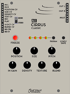
CIRRUS CLASSIC
This is a one to one clone of the CLOUDS Eurorack module from Mutable Instruments.
Module power consumption: ? mA
Inputs
- IN L -
- IN R -
- POSITION CV -
- SIZE CV -
- DENSITY CV -
- TEXT CV -
- REC -
- PLAY -
- V/OCT CV -
- BLEND CV -
Outputs
- OUT L - left output of the stereo signal
- OUT R - right output of the stereo signal
- BUS Ctrl - Midi CC20 CV from Master I/O module
- BUS CV - MIDI pitch signal from the Master I/O MIDI to CV converter
Controls
- FREEZE button -
- PARAM button -
- LOAD/SAVE button -
- IN GAIN -
- DENSITY -
- TEXTURE -
- BLEND -
Patch Suggestions
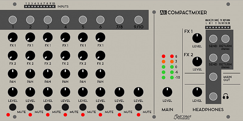
COMPACT MIXER
A useful 10/2 mixer with FX send/return. With both AE and 3.5mm jacks for most connections it is very useful for connecting your AE to other studio gear. The built in Headphone amp could make it useful for live work too.
- Power Consumption: 18mA
- Module Width: 8U
Inputs
Top left of module for AE patch cables inputs, mono 3.5mm socket above each channel column of knobs.
-
1 - Channel 1 input (mono)
-
2 - Channel 2 input (mono)
-
3 - Channel 3 input (mono)
-
4 - Channel 4 input (mono)
-
5 - Channel 5 input (mono)
-
6 - Channel 6 input (mono)
-
7/8 & 9/10 can also be input via stereo 3.5mm jacks
-
7 - Channel 7/8 input (left side stereo, with 8 for 2 "sides" of audio)
-
8 - Channel 7/8 input (right side stereo, with 7 for 2 "sides" of audio)
-
9 - Channel 9/10 input (left side stereo, with 10 for 2 "sides" of audio)
-
10 - Channel 9/10 input (right side stereo, with 9 for 2 "sides" of audio)
On the right side of the module. AE Patch sockets, and 3.5mm stereo sockets available. These could be further stereo inputs to the main signal if you had more you wanted to add, you just lose the mute controls of the 7/8 & 9/10 inputs.
- FX RETURN 1L - left side of stereo with 1R for the right side, or if you want a sound just on the left side of stereo it could be an general input...
- FX RETURN 1R - Right side of stereo with 1L for the left side, or if you want a sound just on the right side of stereo it could be an general input...
- FX RETURN 2L - left side of stereo with 2R for the right side, or if you want a sound just on the left side of stereo it could be an general input...
- FX RETURN 2R Right side of stereo with 2L for the left side, or if you want a sound just on the right side of stereo it could be an general input...
Outputs
All are available as AE patch sockets, or 3.5mm sockets.
- Main L - Left side of stereo of all the combined inputs listed above, levels set by the controls below.
- Main R - Right side of stereo of all the combined inputs listed above, levels set by the controls below.
- FX SEND 1 - Input channels 1-6 can send signal to this output, levels set by their respective FX1 knob.
- FX SEND 2 - Input channels 1-6 can send signal to this output, levels set by their respective FX2 knob.
Headphone Section
- n - 3.5mmm amplified stereo out for headphones, the volume is set by the knob mentioned below. It is not recommended to use it as another output for your recorder etc. but it could be!
Controls
On channels 1-6 the column of knobs do the same thing for each individual channel:-
- FX1 - Sets the level of signal sent to the FX Send 1 output.
- FX2 - Sets the level of signal sent to the FX Send 2 output.
- Pan - Sets the level of the signal going to the Main L and Main R outputs; all the way anticlockwise means the signal is in the L out only, all the way clockwise means the signal is in the R out only. For centre stereo the knob should be pointing almost vertical.
- Level - Sets the overall level of the signal in the main L/R outs but this is impacted by the pan knob above as well.
- MUTE (Button) - when pressed, the input signal is removed from the main outs.
Channels 7/8 & 9/10 have the following:-
- Level - Sets the overall level of the signal in the main L/R outs
- MUTE (Button) - when pressed, the input signal is removed from the main outs.
Main Section.
- Level - this controls the overall volume of main outputs L/R, useful for fade outs and setting record levels for your recorder etc.
- FX1 Level - sets the overall level of inputs FX1 L/R into the Main outputs. This is very useful for setting the general FX level, like reverb for instance, or if you are using the FX inputs to input another stereo sound.
- FX2 Level - sets the overall level of inputs FX2 L/R into the Main outputs. This is very useful for setting the general FX level, like reverb for instance, or if you are using the FX inputs to input another stereo sound.
Headphone section
- '''Level" - this controls the volume of headphones independently of the main volume mentioned above.
Display
Below each MUTE button is an led, when this light is on that channel is excluded from the main mix.
In the Mixer section there are 2 columns of LEDs, green, yellow and red. This shows the level of the main outputs left and right. In general you want the yellow LEDs to be flickering, possibly even the red flickering to be as loud as possible without distortion.
Patch Suggestions
As mentioned in the descriptions above, the FX return inputs can be used to bring in more stereo sources to the overall mix.
The FX sends will work well with the AE MULTIFX as it has a stereo output for the return to the mixer.
Although this mixer is aimed towards providing a 2 channel (stereo) output, there is no reason you could not use it to produce 2 separate mono outputs for further use/processing within the AE.
If you wanted more than one main out to go further within the AE, you could connect the stereo 3.5mm output to a 4 I/O module, then the left and right signals would be on the relevant AE sockets.
You can purchase, or make, splitter cables where you have 2 mono jacks ar one end, and a stereo jack at the other - this may be useful to bring in more external gear, and when connecting the mixer outputs to external gear.

CVADDER-HQ
This module is made to generate CVs which are accurate enough to keep pitch/transposes etc. completely in tune. This could be for 1V/Octave synthesisers, (doesn't have to be the AE modular). This accuracy applies to Oscillators and Sequence modules so could be useful for many purposes.
If the transposition buttons are not necessary and you could use two precision adders, take a look at the 2CVADD-HQ module
Inputs
- 1 to 3 - these three inputs are added together
- IN A4 Neg - this input is deducted from the other three, i.e. it is an inverter.
Outputs
- Out A (x2) - Output of the combined CVs from the 4 inputs.
- OFFSET CV (x2) - this is the voltage provided by the control knob/buttons, e.g. if set to 1 octave it will be 1V at this output.
- MULT - a passive mixer/splitter separate to the module electronics.
Control
- +2 Oct Button - this will add 2V to the CV mix from the inputs, adding 2 octaves if going to an oscillator or filter cutoff.
- +1 Oct Button - this will add 1V to the CV mix from the inputs, adding an octave if going to an oscillator or filter cutoff.
- Free Button - if this button is selected, the knob below selects the voltage added to the mix from the inputs.
- OFFSET Knob - this selects the amount added to the input CVs if the Free' button is selected.
Display
- +2 Oct LED - lit when 2 volts are being added to the output.
- +1 Oct LED - lit when 1 volt is being added to the output.
- Free - Lit when the knob can be used to set the voltage added to the output.
Patch Suggestions
The most obvious use is before VCOs to combine CVs to control pitch. Having 2 outputs each circuit could control 2 oscillators without any help. The inverting input (4) can be really useful here.
The same applies for controlling filter cutoff frequency.
This module can be used as a CV mixer anyway, regardless of destination, again Input 4 can be really handy.
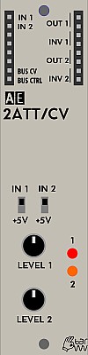
2ATT/CV
2ATT/CV contains two units of a simple level attenuator for any kind of signal.
You can also switch to voltage mode and get a manually controllable CV on the output(s).
Inputs
- IN1 - accept any CV or audio signal
- IN2 - accept any CV or audio signal
Outputs
- Bus CV - CV signal from MIDI
- Bus Gate - Gate signal from MIDI
- 1 - attenuated signal from IN1
- 2 - attenuated signal from IN2
Controls
- Switch IN1/+5 - switch between attenuating signal from IN1 or issue CV between 0-5V
- Switch IN2/+5 - switch between attenuating signal from IN2 or issue CV between 0-5V
- Pot Level 1 - depending on switch 1 attenuate signal from IN1 or select CV level between 0-5V
- Pot Level 2 - depending on switch 2 attenuate signal from IN1 or select CV level between 0-5V
Patch Suggestions
Attenuating CV can be very useful in a lot of situations. A simple example is to control the tonal range of a sample and hold patch, where the output of the S&H can be attenuated to a smaller pitch range before being sent to an oscillator. A common one to to control the level of filter modulation, but the most common is the amount of vibrato (pitch "wobble") by routing the LFO through this module.
This video describes how to use the SAMPLE&HOLD module and makes use of the 2ATT/CV module for controlling pitch:

2CVADD-HQ
The 2CVADD-HQ has 2 separate circuits which are useful for controlling CVs more accurately for pitch, to keep things in tune. This could be for any 1V/Octave synthesisers, (doesn't have to be the AE modular). This accuracy is useful for to Oscillators and Sequence modules, but could be good for many purposes.
If you would like to have transposition buttons to shift by one or two octaves (or an adjustable amount), take a look at the CVADDER-HQ module
Inputs
- A1 to A3 - these three inputs are added together in circuit A of the module
- IN A4 Neg - this input is deducted from the other three on the A circuit.
- B1 to B3 - these three inputs are added together in circuit B of the module
Outputs
- A (x2) - Output of circuit A
- B (x2) - Output of circuit B
- MULT - a passive mixer/splitter separate to the module electronics.
Patch Suggestions
The most obvious use is before a VCO, (e.g. 2OSC/D) to combine CVs to control pitch. Having 2 outputs each circuit could control up to 2 oscillators without any help. The inverting input (4) on circuit A can be really useful here. If you need to control more oscillators the 4BUFFER is recomended rather than just using the Mult as this assists with CV/pitch tracking accuracy.
The same applies for controlling filter cutoff frequency.
This module can be used as a CV mixer anyway, regardless of destination, again Input 4 on circuit A can be really handy.

2CVTOOL
The 2CVTOOL offers two separate units for offset, attenuation and inversion of signals, also known as "attenuverter". This can be useful for all kinds of purposes.
Module power consumption: 2 mA
Inputs
- IN 1 - accepts any CV or audio signal
- IN 2 - accepts any CV or audio signal
Outputs
- Bus CV - CV signal from MIDI (CC20)
- Bus CTRL - CTRL signal from MIDI
- OUT 1 (x2) - attenuverted and offset signal from IN1
- OUT 2 (x2) - attenuverted and offset signal from IN2
- MULT - passive multiple, not connected to the module's circuitry
Controls
- OFFSET 1 - Potentiometer to dial in the offset voltage for channel 1.
- LEVEL 1 - Potentiometer to select the attenuation. This is a bipolar control in that it can reduce the incoming voltage or increase it.
- OFFSET 2 - Potentiometer to dial in the offset voltage for channel 2. This will be added to the incoming CV.
- LEVEL 2 - Potentiometer to select the attenuation. This is a bipolar control in that it can reduce the incoming voltage or increase it.
Patch Suggestions
This is (currently) one of the few modules that can invert a signal so can be invaluable. For example; you want a filter to close as a key is held and then open once released the easiest way to do this is to invert the CV out from an envelope generator. Another common example is inverting a trigger so something else is making noise when the trigger is not "on", useful for rhythm patches...
This module can be useful to provide a knob control to a parameter that doesn't otherwise have one. For example CV2 on the MS20 filter module.
It can also be good with the Joystick module, for instance if you want a CV being controlled by that also have another adjustment.
https://wiki.aemodular.com/pmwiki.php/AeManual/JOYSTICK
Currently only the Mixconsole has CV control of the channel input levels on a mixer; you can use the 2CVTOOL to set a minimum level with the offset, and then the modulation amount (i.e. volume) is controlled by this module's level knob. Excellent with Envelopes but works with LFOs as well....
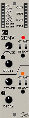
2ENV
2ENV is a dual attack - decay envelope. It can be switched between full sustain (the output remains at full level as long as the GATE input is on) and zero sustain (for percussive envelopes). Another switch (SLOW/FAST) allows selecting the time range. For manual triggering there is a button for each envelope. CV control: Both attack and decay time can be CV controlled; the CV "multiplies" the time by 1...approx. 8 times.
Module power consumption: 8 mA
Inputs
- GT1 - gate or trigger for envelope 1
- ACV1 - accept CV for attack stage for envelope 1
- DCV1 - accept CV for decay stage for envelope 1
- GT2 - gate or trigger for envelope 2
- ACV2 - accept CV for attack stage for envelope 2
- DCV2 - accept CV for decay stage for envelope 2
Outputs
- BUS GATE (2) - Gate signal from MIDI
- OUT1 (3) - CV from envelope 1
- END1 - a trigger CV for when envelope 1 has finished
- OUT2 (3) - CV from envelope 2
- END2 - a trigger CV for when envelope 2 has finished
Controls
The controls are grouped into 2 identical groups marked with the number 1 and 2 for each of the individual envelopes. We only describe the controls for one group as they work exactly the same for the other group.
- ATTACK Knob - change the attack time from 0 (percussive) to either 2 or 16 seconds depending on FAST/SLOW switch
- DECAY Knob - change the decay time from 0 to either 3 or 24 seconds depending on FAST/SLOW switch
- GT/TR Switch - switch between GATE or TRIGGER mode. When in GT mode the envelope will rise according to ATTACK knob or ACV2 value for as long as signal on GTx is high and once signal drops then decay part will be initiated. When in TR mode the attack part of the envelope will play out until it reaches full level and then initiate decay part.
- FAST/SLOW Switch - changes time multiplier for attack and decay times. See above.
- Trigger Button - sends a trigger signal to start the envelope. Always acts like a trigger even when GT mode is active. Unmarked on front panel.
Patch Suggestions
Envelopes are one of the basic modulation sources in subtractive synthesis. They are usually used to modulate amplitude, pitch or a filter. Often you would trigger the envelope from the BUS GATE which means that if a key is pressed on a MIDI keyboard the envelope would activate and open a VCA for instance and then slowly (or fast) close it once the key is released. The envelope can also be triggered from an LFO or TRIQ164 for rhythmic or percussive uses.
The 2ENV can also trigger itself when the output ENDx is patched into the GTx. This can make an envelope into a slow moving LFO (low frequency oscillator), or oscillator in audio range, with varied waveforms depending on the attack/decay settings.
This video explains the usage of the AE Modular 2ENV module on a very basic level:
Using the 2ENV as a voltage-controlled trigger delay in a feedback loop:
Patching a swinging rhythm with the 2ENV as a trigger delay:

2LFO
The 2LFO module has two LFO units with different features and generates modulation voltages mostly below the audio range.
The waveform of the first LFO can be continuously morphed from rising saw to triangle to falling saw by turning a knob.
The pulse output of the second LFO can be shaped with the pulsewidth knob for different pulse lengths.
Module power consumption: 5 mA
Inputs
- SYNC 1 - resets the LFO 1 waveform when a trigger pulse is received
- SYNC 2 - resets the LFO 2 waveform when a trigger pulse is received
- PWM 2 - control voltage input for pulse width modulation of PULSE wave output of LFO 2
Outputs
- SQUARE 1 - low frequency square wave with fixed width (half cycle)
- TRIANGLE / SAWTOOTH 1 - low frequency triangle or sawtooth wave
- SQUARE 2 - low frequency pulse where pulse length is set by the PULSEWIDTH knob
- TRIANGLE / SAWTOOTH 2 - low frequency triangle or sawtooth wave
- BUS CV - control voltage signal from MIDI
- BUS CTRL - CTRL signal from MIDI (CH1 - CC20)
Controls
- RATE 1 knob - frequency control for LFO 1
- SHAPE knob - controls a smooth transition from rising saw to triangle to falling saw waveforms for LFO 1
- SLOW / FAST switch 1 - switch between two frequency ranges for LFO 1
- TRIANGLE LED 1 - visual reference for the TRIANGLE / SAWTOOTH output for LFO 1
- RATE 2 knob - frequency control for LFO 2
- SLOW / FAST switch 2 - switch between two frequency ranges for LFO
- TRIANGLE / SAWTOOTH switch - choose the waveform of the TRIANGLE / SAWTOOTH output for LFO 2
- PULSEWIDTH knob - set the pulse width of the output for LFO 2
- PULSE LED - visual reference for the PULSE output for LFO 2
Patch Suggestions
LFO can be used for modulating other oscillators (FM), VCAs (AM), filters, etc. But may also be used as clock or gate.
Patching two unsynched LFOs through a logic module then to a sequencer creates interesting uneven rhythms. Changing their pulsewidth creates new rhythms.
Combined LFOs connected to CV switches or a multiplexer results in a simple and versatile trigger sequencer.
When cranked up to audio range (RANGE knob all the way to the right in FAST mode) may be used as audio oscillator.
This module is very similar to the single LFO module. Please see a video for further info about LFOs on that page.
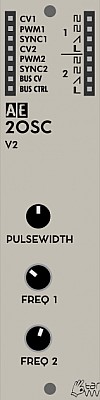
2OSC
This module has been discontinued and is no longer in production, replaced by the OSC2/d.
The 2OSC is a dual analog oscillator that produces square, sawtooth and pulse waves per independent oscillator. Due to its analog nature it is not very stable and can best be used for modulation, drones or percussive sounds where accurate pitch is not as important. It does have a big, raw sound though.
Inputs
- CV1 - control voltage input for pitch frequency
- PWM1 - control voltage input for pulse width modulation of square wave output
- SYNC1 - sync input to synchronise this oscillator with another one
- CV2 - as above but for the second oscillator
- PWM2 - as above but for the second oscillator
- SYNC2 - as above but for the second oscillator
Outputs
- BUS CV - MIDI pitch signal from the bus
- BUS CTRL - MIDI Control CC signal from the bus
- 2x Square wave 1 & 2-
- Saw wave 1 & 2 -
- Pulse 1 & 2 -
Controls
- PULSEWIDTH1 - only the pulse width of the first oscillator can be controlled via a knob. However both oscillators can be controlled via the PWM inputs via control voltage.
- FREQ 1 - frequency (pitch) of the first oscillator
- FREQ 2 - frequency (pitch) of the second oscillator
Patch Suggestions
This video by Synths & Things explains the ins and outs of this module really well: https://youtu.be/2YXKdagWlbg
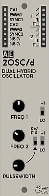
2OSC/d
The 2OSC/d module contains two 1V/octave hybrid oscillators. It is designed as a hybrid digital/analog module. The oscillator frequencies are determined digitally and are therefore quite stable and have good tracking. The output waveform itself is created analog. The design causes the waveform to get a bit gritty at higher frequencies, but not devolve into "digital noise" - it's the character of this thing!
Module power consumption: 25 mA
Inputs
- CV1 - Frequency CV for OSC 1
- PWM1 - CV for Pulse Width Modulation for OSC 1
- SYNC1 - Sync control for OSC 1
- CV2 - Frequency CV for OSC 2
- PWM2 - CV for Pulse Width Modulation for OSC 2
- SYNC2 - Sync control for OSC 2
Outputs
- BUS CV (2x) - located on the left patch bay it outputs the MIDI CV from the Bus.
- Saw 1 (2x) - Sawtooth wave output for OSC 1
- Square 1 - Square wave output for OSC 1
- Sub Square 1 - Square Sub Oscillator for OSC 1, this is almost one octave down from the square output.
- Saw 2 (2x) - Sawtooth wave output for OSC 2
- Square 2 - Square wave output for OSC 2
- Sub Square 2 - Square Sub Oscillator for OSC 2, this is almost one octave down from the square output.
Controls
- FREQ 1 knob - Frequency for OSC 1
- HIGH / LOW switch 1 - switch between two frequency ranges for OSC 1
- FREQ 2 knob - Frequency for OSC 2
- HIGH / LOW switch 1 - switch between two frequency ranges for OSC 2
- PULSEWIDTH knob - set the pulse width of the output for OSC 2
- PW FIX switch – in upper position the pulse width is fixed for OSC 2
Patch Suggestions
The usual patch would be either direct to the filter, or via the 4ATT/Mix if you are combining more than one oscillator, noise etc.
Audio pitch modulation of filters and pitch can be really good, the latter can be FM synthesis in some circumstances.
This video explains how to use this module in a very basic patch.
There is also more on the 2OSC module page:-
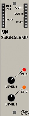
2SIGNALAMP
A signal amplifier module, i.e. you can make a signal louder/stronger. There are 2 separate circuits in this module, with a maximum gain of 15-1.
Module power consumption: 2 mA
Inputs
- In 1 - input for circuit one.
- In 2 - input for circuit two.
- Mult - a passive mixer/splitter completely separate to the module circuits.
Outputs
- Out 1 (2) - output of circuit one.
- Out 2 (2) - output of circuit two.
- Mult - a passive mixer/splitter completely separate to the module circuits.
Please note that the input side Mult is separate to the output side Mult and both are bidirectional (i.e. use any socket(s) for in or out).
Controls
- Level 1 knob - sets gain level of input 1, i.e the more clockwise you turn the knob the louder the output. If the Clip LED lights you have hit the maximum level the AE Modular can cope with
- Level 2 knob - sets gain level of input 2, i.e the more clockwise you turn the knob the louder the output. If the Clip LED lights you have hit the maximum level the AE Modular can cope with
Patch Suggestions
As Robert suggest on the Tangible Waves website, this module is usually used to boost the triangle wave signal from the VCO, or external signals (usually via the 4 I/O module).
It can also be useful to boost the general signal level before the AE modular goes to an external mixer or recorder etc. It can boost signals coming into the AE also, but please put them through the 4I/O or Master/Power modules first.
It can also be used as a simple mixer by putting the 2 outs into a Mult with another cable going from there to the next stage, can be useful for VCOs to save your 4ATT/Mix module for other work.
It can be overdriven to creating signal alteration/distortion.....

2TONE
2TONE is a dual bass-treble tone control, that is a quite useful companion for the MIXCONSOLE, to shape the overall spectrum of individual signal paths.
Module power consumption: 4 mA
Inputs
- IN1 - Audio signal for channel 1
- IN2 - Audio signal for channel 2
Outputs
- Out 1 - Adjusted signal for channel 1
- Out 2 - Adjusted signal for channel 2
Controls
- HIGH 1 - Adjust the high frequencies for channel 1
- LOW 1 - Adjust the low frequencies for channel 1
- HIGH 2 - Adjust the high frequencies for channel 2
- LOW 2 - Adjust the low frequencies for channel 2
Patch Suggestions
Use this to raise or lower certain frequencies of a sound source before sending it to the MIXCONSOLE or other mixing module.
It can be useful to free up a filter module is some cases, e.g. roll the top off a bass pitch to make it deeper sounding.
If you want to risk your speakers/headphones, you can feed one channel's output into the input of the other channel so you boost the signal twice.
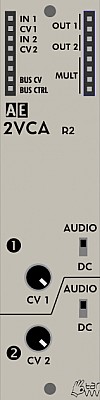
2VCA
2VCA contains two separate VCA (voltage controlled amplifiers); the classic module to shape the volume of a sound that is fed to IN by a control voltage, e.g. from an ENV to the CV input. If zero voltage is provided, the VCA stays closed and the IN signal doesn't go through. As the CV rises so does the signal strength going through to the output.
A switch determines the operation mode (DC/CV or audio), choosing the right position can reduce/avoid pop's with short attack envelopes.
An additional knob for each VCA attenuates the level, if necessary.
Module power consumption: 5 mA
There is also a 4VCA module available.
Inputs
- IN1 - accept audio or control signal to be amplified or attenuated
- CV1 - accept CV for amplitude modulation of IN1 signal.
- IN2 - accept audio or control signal to be amplified or attenuated
- CV2 - accept CV for amplitude modulation of IN2 signal
Outputs
- OUT 1 (2) - amplified or attenuated signal from IN1
- OUT 2 (2) - amplified or attenuated signal from IN2
- BUS CV - CV signal from MIDI
- BUS CTRL - CTRL signal from MIDI (CH1 - CC20)
- MULT - Passive signal multiplier, all sockets are bi-directional
Controls
The controls are grouped into 2 identical groups marked with the number 1 and 2 for each of the individual VCA. We only describe the controls for one group as they work exactly the same for the other group.
- CV Knob - signal level attenuation.
- AUDIO/DC Switch - switch between AUDIO or DC mode.
Patch Suggestions
As stated above, the most common use is patching an oscillator to any IN and an envelope to the corresponding CV.
But VCAs may be used for an infinite number of purposes. They can be used to modulate any signal's amplitude, be it control or audio rate. Here are some ideas:
- Patching an audio signal both into the IN and the CV inputs results in AM synthesis.
- Patching separate audio signals to VCAs/CV through a mixer you get a wave shaper.
- Patch an LFO to IN1 and another LFO to CV1. The second LFO then modulates the amplitude of the first one, providing some variety to it.
VCAs are simple and absolutely versatile. That's why "you can never have too many VCAs".
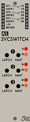
3VCSWITCH
This module gives you 3 separate switches, controllable from the buttons on the front panel or via the gate inputs. Each circuit can be used bidirectionally; i.e a signal can be sent to one of two destinations or one of two signals can be selected to go to the output.
Module power consumption: 4 mA
Inputs
- IO1 - Circuit 1's in/out going to/from 1A or 1B
- Gate1 - a +5V pulse here switches from 1A to 1B or from 1B to 1A
- IO2 - Circuit 2's in/out going to/from 2A or 2B
- Gate2 - a +5V pulse here switches from 2A to 2B or from 2B to 2A
- IO3 - Circuit 3's in/out going to/from 3A or 3B
- Gate3 - a +5V pulse here switches from 3A to 3B or from 3B to 3A
- +5V - actually an output giving +5V, the maximum the AE Modular can deal with. Very useful for further processing via this module or others for modulation.
- Bus Gate - This output gives a +5V signal whilst an external midi device key on is pressed, via the Master module.
Outputs
- 1A - Circuit 1's A in/out
- 1B - Circuit 1's B in/out
- 2A - Circuit 2's A in/out
- 2B - Circuit 2's B in/out
- 3A - Circuit 3's A in/out
- 3B - Circuit 3's B in/out
Controls
The panel is marked 1,2 and 3 for each circuit, the controls are the same for each.
- Latch button. - When this button is pressed it moves the connection from A to B or B to A.
- MMT button. - When this button is pressed output/input on A is switched to B, or vice versa, but only whilst the switch is pressed, i.e. it is a momentary button.
Patch Suggestions
There is a patch challenge for this module on the forum. Here you can find more interesting uses of this module: http://forum.aemodular.com/thread/313/patch-challenge-pulling-old-switcheroo
This module is excellent for providing variation in rhythms/ sequences by cutting a trigger in or out via the buttons if "playing" the AE modular, or the gate inputs - the latter can be done with an LFO, envelope or one of the sequencer modules. It works really well with the TRIQ164 and the (discontinued) Step 10 modules. The SEQ16 module main out can work with a bit of care, but it works really well using of one of the various gate outputs to the 3VCSwitch, especially combined with the Logic module to vary things further.
It is useful where you want to automate switching between 2 audio paths, (e.g. 2 different filters) as part of a patch.
It can be used to create Stereo from mono by going 1 in to 2 out, (thanks to Tuesday Night Machines for this one). He suggests "now use a square VCO to quickly switch that audio signal between the ears for crazy effects".
Other trigger/ trigger variation modules, like the Divider (discontinued), Trip, MM Divider and, particularly the Topograf combine with the 3VCSwitch for endless possibilities.
Below is a video by the5thvolt a with various patch ideas: https://youtu.be/ddANhDYMVh0
This video is for a Eurorack module similar to the 3VCSWITCH, and so gives some more ideas you may want to explore.
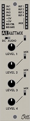
4ATTMIX
This module offers four separate attenuators to reduce signal strengths and also comes with a mix output.
There is the same module with faders rather than knobs, which can be really useful for audio mixing live etc. 4ATTMIX Fader
Module power consumption: 2 mA
Inputs
- IN 1-4 - signal inputs for each attenuator
Outputs
- OUT 1-4 - individual attenuator outputs
- MIX - The 4 In signals combined, dependent on the controls and switch settings below.
- 2x +5V - static 5V outputs
- Bus Ctrl - Midi CC20 CV from Master I/O module
- Bus Gate - gate signal from the Master I/O MIDI to CV converter
Controls
- LEVEL 1-4 potentiometers - reduce the strength of the incoming signals 1-4
- MIX switches - adds/ removes the relevant input signal from the mix outputs.
- DC AUDIO switch - switches the module between DC-coupled (0-5V) and AC-coupled (signal centered around 2.5V, sometimes useful for audio signals) operation
Patch Suggestions
-
You can create a tweakable control voltage by patching a +5V output into an input then attenuate it with the relevant knob to suit your needs. The output is then patched to what you are wanting to control. This is useful when another module offers a CV input which you would like to control with a knob and doesn't have a CV level already built in, (e.g the PWM 1 and 2 inputs on the 2OSC/d module).
-
The individual attenuator outputs and the mix output work at the same time, so you can have a mix of different control voltages as well as their individual signals for further use or processing by other modules.
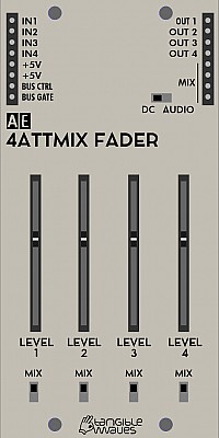
4ATTMIX FADER
4ATTMIX FADER is functionally identical with the 4ATTMIX module, but instead of potentiometers there are faders which are convenient in certain situations where values are to be changed simultaneously, It is also easier to see the current levels at a glance, excellent for VCO mixing.
Module power consumption: 2 mA
Inputs
- IN 1-4 - signal inputs for each attenuator
Outputs
- OUT 1-4 - individual outputs for the relevant signal in.
- MIX - Signals from inputs 1 to 4 combined as set by controls below.
- +5V (x2) - static 5V outputs
- Bus Ctrl - Midi CC20 CV from Master I/O module
- Bus Gate - gate signal from the Master I/O MIDI to CV converter
Controls
- LEVEL 1-4 faders - reduce the strength of the incoming signals 1-4
- MIX switches - adds/ removes the input signals from the mix output
- DC AUDIO switch - switches the module between DC-coupled (0-5V) and AC-coupled (signal centered around 2.5V, sometimes useful for audio signals) operation
Patch Suggestions
Please see the 4ATTMIX module page.

4BUFFER
Many AE modules have Mult sockets where you can combine or split signals. This isn't always reliable in terms of what the end result is, especially if you are wanting the output CV for pitch control. This is where the 4Buffer Module comes in.
You can combine up to 4 signals (no mixer controls) or make a signal up to 8 separate outs. It can also do 2 separate input pairs (i.e. 2 to 1), and 4 separate one input to two outputs.
If you want to control the level of the inputs being combined then you need to look at the 4ATTMIX and Polamix modules.
- https://wiki.aemodular.com/pmwiki.php/AeManual/POLAMIX
- https://wiki.aemodular.com/pmwiki.php/AeManual/4ATTMIX
- https://wiki.aemodular.com/pmwiki.php/AeManual/4ATTMIXFADER
Module power consumption: 1 mA
Inputs
- IN1 - input for channel 1.
- IN2 - input for channel 2.
- IN3 - input for channel 3.
- IN4 - input for channel 4.
Outputs
- OUT1 (x2) - output of channel one.
- OUT2 (x2) - output of channel two.
- OUT3 (x2) - output of channel three.
- OUT4 (x2) - output of channel four.
On left (usually input) side
- B.Crtl - the CV generated on Midi CC20, usually a mod wheel on a connected Midi keyboard via the Master module .
- B.CV - the CV generated by a key being pressed on a Midi keyboard attached to the master module.
Controls
- Link 1-2 - This switch joins inputs 1 and 2 together, so outputs 1 and 2 carry the combined signal.
- Link 2-3 - This switch joins inputs 2 and 3 together, so outputs 2 and 3 carry the combined signal. If the Link 1-2 switch is also on then all 3 inputs are combined and sent to the three outputs.
- Link 3-4 - This switch joins inputs 3 and 4 together, so outputs 3 and 4 carry the combined signal. If Link 2-3 switch is also on, then inputs 2,3 & 4 are combined and sent to outputs 2,3 &4. If Link 1-2 is on as well as Link 2-3 then all 4 inputs are combined over all 8 outputs sockets.
Patch Suggestions
The most obvious use to to provide CVs to multiple oscillators from a connected Midi keyboard, but applies for anytime you want the same pitch CV to go to more than one VCO, (it can be good for that CV to go to a LFO module as well).
It can be used to mix any CVs together, saving your 4ATTMIX modules etc. Mixing CVs together is really useful where a module has one CV input.
This module combines with other CV manipulation modules, e.g. 2CVTOOL and SLEW/EDGE.
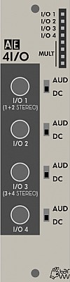
4I/O
An extremely useful module to have if you want to interface other equipment with your AE modular. The most important job is to prevent a CV outside the 0 to +5 volts range from entering the AE system as this would damage it.
Inputs
- I/O 1 - 3.5mm jack socket - mono signal sent to I/O patch socket 1
- I/O 2 - 3.5mm jack socket - signal sent to I/O patch socket 2
- I/O 3 - 3.5mm jack socket - mono signal sent to I/O patch socket 3
- I/O 4 - 3.5mm jack socket - signal sent to I/O patch socket 4
They are labelled I/O as you can also send the signal input into the AE patch in/outs (in the AE system's usual location for outputs) and out to your external equipment via these sockets
If a stereo 3.5mm plug is used into sockets 1 or 3, the signals are output on patch in/outs 1/2 and 3/4 respectively.
Outputs
-
I/O 1 - This will output the signal from the I/O 1 3.5mm socket above, or send one to it.
-
I/O 2 -This will output the signal from the I/O 2 3.5mm socket above, or send one to it.
-
I/O 3 - This will output the signal from the I/O 3 3.5mm socket above, or send one to it.
-
I/O 4 - This will output the signal from the I/O 4 3.5mm socket above, or send one to it.
-
Mult - A passive mixing/ splitter with no connections to main module circuits.
Controls
- AUD/DC Switch - 1 for each 3.5mm socket - selects audio signal or CV type signal. For the AE this means a CV is 0 volts to 5V, with 0 as the base, for audio it "rotates" around 2.5 volts but still is 0 to 5 volts. If things are quite as expected, try the switch in the other position.
Patch Suggestions
This module is great for bringing in other synth's modulation CVs, (especially envelopes where you can do more complex things than the AE currently can). By using 2 or more of the 4 channels, you can bring in an external Gate/CV from a sequencer or keyboard.
It can also be used to sync non midi equipment with the AE's sequencer modules.
It can also be useful to bring in external audio for processing within the AE system.
It's also great for sending the AE's audio out to a mixer or recording device with line level. Just patch in the output of the MultiFX into I/O1+2 and then you can use a stereo cable from the first jack without the need of splitter cables as you would have to use on the master module.
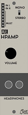
HPAMP
This module provides an output for 1 or 2 pairs of headphones. It means you can listen to the AE modular without external studio equipment.
Module power consumption: 15 mA
Inputs
- In L - left stereo signal. Also the mono input in conjunction with the mono/stereo switch
- In R - right stereo signal
- Mult - passive mixer/splitter, no connection to circuits in this module.
Outputs
2 x 3.5mmm stereo headphone sockets
Controls
- Mono/Stereo Switch - If working in mono, this switch allows the Left input signal to go to both headphone speakers.
- Volume - Level of headphone sound, same for both outputs.
Patch Suggestions
This module is essential if you want to play with just your your AE modular, and is very useful for using when doing mobile synthing - e.g. on batteries in the garden or wherever. Other equipment can be brought into the AE via the 4 I/O and mixed within the AE before out to the HP Amp module if needed.
The Multi-FX module is great for taking a mono signal and making it stereo before that goes to the HPAMP module. Another option is the Mixconsole.
NOTE: due to the signal amplification there can be a noticeable hum or noise when using this to connect to line level equipment like recorders or mixers. For mixing and recording it is better to use the outputs from the Master module or 4I/O which are line level.

JOYSTICK
The JOYSTICK module can mix up to 4 CVs, these are provided at its inputs. It can also generate its own CVs so can easily provide basic mod wheel type control of pitch (vibrato) through to complex, live mixing of audio (with other modules).
Inputs
- CV1 - input for Q1 of the joystick.
- CV2 - input for Q2 of the joystick.
- CV3 - input for Q3 of the joystick.
- CV4 - input for Q4 of the joystick.
- MULT - a passive mixer/splitter. This is very useful on this module if you are wanting the same signal in more than one input; put the signal in here, then then (short) leads to the inputs you want to feed.
Outputs
- Q1 - Either the output from input 1, or CV voltage, controlled by how close the joystick is to Q1 on the front panel.
- Q2 - Either the output from input 2, or CV voltage, controlled by how close the joystick is to Q2 on the front panel.
- Q3 - Either the output from input 3, or CV voltage, controlled by how close the joystick is to Q3 on the front panel.
- Q4 - Either the output from input 4, or CV voltage, controlled by how close the joystick is to Q4 on the front panel.
- CV X - A voltage dependent on the side to side position of the joystick
- CV Y - A voltage dependent on the up/down position of the joystick
- CV MIX - the 4 inputs combined into one CV signal, controllable with the joystick.
- Gate - A gate signal is proved when the joystick is pushed
Controls
- Overlap switch - If overlap is selected, the relevant CV is controlled over the whole movement of the joystick from its side (quadrant) to the other. If overlap is off, then zero/no volume is when the joystick is in the centre position.
- Input Mix/CV Source switch - Input mix means the joystick controls whatever is being fed into the 4 inputs. CV source means the joystick produces voltages dependent on its position, each one of the 4 outputs being different most of the time!
- The Joystick itself!
It is important to remember it remains in each position - there is no automatic "return to centre". Also it can generate a gate signal (own output) by being pressed.
Patch Suggestions
For audio mixing with the joystick, select CV source, then patch the 4 outputs to separate VCAs (e.g. 4VCA), you have 4 individual controllable signals which you can mix together with any of the mixer modules (e.g. 4ATTMIX). The MIXCONSOLE module can have the signal straight from the Joystick module to control channel levels.
The joystick can be just like a normal mod or pitch wheel; by taking the Y output to what you want to control by the up/down movement. If this goes to the CV in of a VCA, then the signal level of what is input to the VCA will be controlled - e.g. input a LFO with the output going to a VCO the joystick will control vibrato.
You can do this with the side to side movement (x axis) as well, controlling 2 parameters at once - this could be filter cutoff, an oscillator level, LFO speed etc etc etc...
The trigger can be used for a modulation envelope (e.g. pressing the button triggers a slow ENV which varies the filter cutoff), can be good for the Algodrone module and for manual triggering of percussion sounds.
555
Keurslager Kurt - 555 Oscillator
(needs more input)..
Kurt’s Dead Band
Kurt's Dead Band module is a unique waveshaper, it is able to shape both audio and CV/DC inputs. It will introduce a so-called 'Dead Band': a portion of your input wave will be snapped to one voltage of your choice. In this way, you can introduce a 'pause' in your waveform. On audio it can give phaser-like effects, but depending on the complexity of the input waveform, it can also sound like a unique kind of filter. On CV you can introduce a steady 'pause' in your CV signal, or you can introduce a sudden vertical 'bump' if you use the vertical dead band setting. You can determine the location of the Dead Band (eg at 2V), and also the size around that voltage that gets snapped to the preset voltage. The location can be controlled with CV input.
You can purchase the module here: https://www.tindie.com/products/keurslagerkurt/kurts-dead-band/
Inputs
- In: Four inputs that get actively mixed together before they enter the waveshaper circuit, much like the B section of the 4-4 Mixer. Input can be both audio or CV/DC.
- CV: Four CV inputs that get actively mixed together before they enter the waveshaper circuit. CV is used to control the location parameter of the dead band.
Outputs
- Out: The inputs with an introduced dead band.
- CV Mix: The four CV inputs that are mixed together, useful as an additional mixer or to use further on with other modules.
- Mult: 6 passive mult patchpoints that are connected.
Controls
-
Location: The location of the dead band, ranging from 0V to 5V. Any input CV amount gets 'added' to this fixed voltage.
-
Size: The range or width of this dead band, centered around the location. If you turn it full left, there should be barely any effect. Fully to the right, audio should be gone or almost gone, depending on the input volume.
-
CV: An attenuation knob for the input CV, much likes the knobs found on AE Filters. It determines how much the CV input influences the 'Location' parameter.
-
Gain: This knob acts as a final gain after the dead band is introduced. However, it should be noted, that it does not act like your usual 'gain' or amplification. Depending on where you deadbanded your input, this parameter will act differently. It will work as a classic gain (ie volume boost) only when your circuit is deadbanded around 2.5V, so with the 'Location' knob in its central setting. This knob is particularly useful when you feed eg an envelope as input to the module. Tweaking this parameter will make sure that the 'start' of your envelope is at 0V, and not at eg 1V (which would otherwise give you a slight sustain when you drive a VCA with your envelope). Experimenting is key with this parameter, it is a dangerous one to tweak in the middle of a live performance!
-
The switch allows you to change the dead band from a horizontal to a vertical dead band. A horizontal dead band introduces a horizontal 'pause' in the waveform, while a vertical dead band introduces a sudden 'bump' in voltage.
Patch Suggestions
The Dead Band module is very much a 'building block' module. Depending on what you feed it, it can give very different results, so experimenting and trying different out of the box stuff is the way to go! But some basic ideas to get you going:
You can patch a simple VCO into the module, and use a slow LFO as CV input to get some subtle timbral changes in your waveform. It works best with the "Size" parameter at lower values, and the 'Location' parameter somewhere between one quarter and three quarters. This should give you some phaser like results. Tweak the CV attenuation knob to determine the amount of FX.
If you swap the LFO from the previous patch with another VCO, you will modulate the location parameter at audio rates, which also gives very interesting results! Now you can try patching different CV inputs at the same time, which mixes them together. Or you can check out the different timbre when using the vertical setting.
If you input a more complex waveform, like a mix of some VCO's and white noise, or a complex oscillator like the Algodrone, you will find that the Dead Band can have some filter like qualities. If you now input an envelope in the CV input, you will find that it can act like a strange kind of VCA depending on how you tweak the settings!

Five Steps
This is a 5 step "arpeggiator", being modular it's a bit more complicated than that.
It takes a CV as input, for example a triangle LFO, and converts it into a stepped CV as output. You can control the five possible CV values that it can output with the five knobs on the front panel. This way, each input gets converted to one of the five output CV’s, generating an ‘arpeggio’ when used for note CV.
The second input voltage (Root CV) gets added with all five values of the output CV. As such, it effectively ‘transposes’ your complete sequence.
This is Kurts Tindie page for this module, his first not sold as a kit.
Inputs
- ARPCV - The CV used to generate the arpeggio. This is usually an LFO or envelope, but any can be used, even audio. When you use a triangle LFO, your output will be a rising & falling arpeggio. An input LFO that is a ramp up, would be only a rising arpeggio, and so on.
- ROOTCV - This CV is added to the CV generated by the knobs. If you start with zero volts and add, it will be a transpose up; if you start with a voltage and change it to zero it will be a transpose down.
- MULT - a passive mixer /splitter nothing to do with the module's main circuits.
Outputs
- Steps (x2) - The stepped CV output. You can see this as the ‘note cv’ from your arpeggio, but it can of course be used to control anything!
- Trigs - +5V trigger to coincide with each step, for VCAs etc.
- 2 - +5V when steps 2 to 5 are playing.
- 3 - +5V when steps 3 to 5 are playing.
- 4 - +5V when steps 4 or 5 is playing.
- 5 - +5V when step 5 is playing.
Controls
The knobs are not numbered but relate to the steps of the arpeggio generated from 1 to 5 inclusive. From Kurt's page...
''To start, I would like to point out that this version contains a mistake in the PCB wiring. But as I have 20 of these around, I pretty much have to sell them, because it was quite an investment.. The mistake is as follows: potentiometer/knobs 2-5 are in reverse order. So the knobs from top to bottom are: 1 - 5 - 4 - 3 - 2. Other than that, the module works perfectly!"
Each Knob sets the voltage added to the previous voltage for each step. So changing knob 1, (the top one), will change all your output notes, effectively tuning your whole arpeggio. Changing knob five will only change the last (or rather, highest) note.
The module basically consists of 4 comparators with fixed thresholds at 0.833V, 1.66V, 2.5V and 3.33V. When you input a CV below 0.833V, the output will be the voltage dialed in with the first knob. When you input a CV between 0.833 & 1.66V, the output CV will be the sum of the voltage of knob 1 & 2. When you input a CV between 1.66V and 2.5V, the output will be the sum of knob 1, 2 & 3. And so on. This way you can create a stepped CV out of a continuously changing voltage (LFO, envelope,..). Or you can use it with the Wonkystuff RBSS as input to fix the changing values to five values of your choice.
Patch Suggestions
The T.W. Quantizer module can be good if you want the CVs from this module tuned to a scale for VCOs, Solina etc.
Kurt here! One of my personal favorite patches with the Five Steps: use an LFO to generate an arpeggio of choice. If you use the Sync input of the LFO to sync it with eg the first beat of your rhythm, your arpeggio will stay nicely on the beat with some tweaking of the lfo speed. Then you can use an Wonkystuff RBSS, clocked to the beat or not, to generate transpositions, by running the RBSS CV out into the ‘Root CV’ in of the Five Steps. Its a good idea to run the RBSS out through an attenuator (eg 2ATT/CV) to limit the range of the transpose to something musical. The output of the Five Steps can be run through the TW Quantizer in order to make the transpositions in key & musical. You can also use the SEQ8 into the ‘Root CV’ input, to generate transpositions that you can control with the SEQ8 CV’s. If you tune this well, you can get great results without the need for the Quantizer.
Fun with audio input: if you input an audio signal into Arp CV in, you will effectively reduce the audio’s ‘bitrate’ to five bits. Your waveform will be reduced from a continuous signal to just 5 possible voltage values, which you can see as the ‘five bits’. If you dial knobs completely down, you will reduce the bits even further. If you use only one knob and tune the others down, you effectively get a 1-bit signal, in other words: a PWM’ed square wave. Can give interesting textures with FMOS as input, or triangle waves, ramps,.. Does not work well with square waves, as these are already 1 bit waves.
With the many possibilities for CVs generated from the module, several modules would partner well with it, including Kurt's own Great Divide and most modules on the T.W. website listing of CV generating/manipulation modules...
https://www.tangiblewaves.com/store/c12/CV_Generation_%2F_Manipulation.html
Zeno (Keuerlagerkurt) has done an introductory video:-

The Great Divide
This is an R2R circuit, quite versatile for mixing CV and trigger signals. There are two independent circuits in this module, with a small variation.
This is Kurt's Tindie page where you can buy the kit.
It is based on Olegtron's R2R circuit; a quote from his page:-
"The first principle is, that when you connect a signal to any of the jacks, it affects the voltages in all the other jacks.* The ground connection has got a kind of a stabilizing effect, since the jacks near to ground are connected to ground with a smaller resistance. As more resistors are added to the series, the ground connection gets more distant. So, a signal plugged to a jack near ground has less overall effect compared to a signal plugged further from ground. Same principle goes when you plug more signals in: the signals get mixed together in relation to each other and the distance to ground. That’s how inputting signals work.
If you wish to get some signals out of the module, they’re available all around the place: the unused jacks provide each a different mixture of the signals, according to how near the signals are to each other, and to ground. The signals plugged to jacks near to the output are emphasized in the mix, and the output level is likely to be smaller when taken from near the ground."
For more info, https://www.olegtron.com/olegtron-r2r-1
Inputs/Outputs
The left side is circuit one, The right side is circuit two. They are not connected unless you put a patch lead from one side to the other. All sockets can be inputs or outputs.
The only difference is that circuit two lacks the "1" socket, and circuit one lacks the "128" socket, otherwise they are functionally the same.
Controls
What the module does is affected by what sockets you put the input(s) and take the output(s) from. The resistors in the module will cause a voltage drop and, in general, the further apart the input and outputs are plugged in the more variation/change you will get.
Patch Suggestions
It is excellent producing multiple triggers from one input, which can be syncopated, or not....
It can generate a range of CVs for pitch or other duties from one input, and will mix audio or CVs in different ways depending in where they are plugged in, in relationship to the output....
R2R mixing is done by choosing different inputs: 1 is the quietest (lowest voltage), 128 the loudest (highest voltage).
It really is a module to experiment with, highly recommended for larger AE systems.
Quad boost
Kurt’s Quad Boost
Kurt’s Quad Boost is a module consisting of four transistor amplifier circuits, inspired by the old-school ‘LPB-1’ guitar pedal. Each amplifier circuit has its own dedicated ‘Boost’ knob that controls the input volume. The amplification has a distinct ‘transistor sound’. Due to the non-linear nature of this simple component, it is by no means a clean boost at all. Depending on the input volume, you will get everything in between crispy high end accents and deep low-end fatness.
This module is designed and distributed by Keuerslager Kurt and you can purchase the module here: https://www.tindie.com/products/keurslagerkurt/kurts-quad-boost/
There are four separate inputs that each lead to their own amplification circuit.
Outputs
The outputs of the four amplification circuits.
Controls
Each of the four boosts has its own dedicated input volume knob. It should be noted that this knob does not act as an attenuator, it does not completely silence the incoming signal when turned fully left. Rather, it gives you a control for the amount of ‘drive’ or ‘clipping’ that the circuit gives.
Patch Suggestions
The most straight-forward use of the Quad Boost is to boost signals that are lower in volume, like the triangle or saw wave from the 2Osc module. You will notice that you can get some fairly clean amplification of these waves, but also some more ‘colored’ sound depending on the amount of ‘Boost’ you set. If you input already ‘loud’ waves, like the square waves, the effect will be less noticeable, as these are already at the maximal ‘internal’ volume of the AE system (i.e. 0-5V).
A more interesting approach to exploit the transistor sound is by controlling your incoming waves with a VCA module. Depending on the input volume, the timbre or tone of the output can drastically change. So setting a slow LFO to modulate the incoming volume via the VCA, will create an interesting shift in tone and make your patch come alive. More drastic volume changes, for example using the 2Env for short notes, can also give really musical results.
A sound demo patching different volumes of the same triangle wave in the Quad Boost:
It is also worth noting that the circuit might behave differently depending on the module you patch behind it. Don’t be afraid, you can’t break anything! But if you use ‘unbuffered’ modules right after the Quad Boost output, you might notice some volume drops. This is due to the simplicity of this circuit (for the electronic geeks: it has a rather moderate output impedance ranging from 5k to 50k depending on the specific resistor values you use). I myself have noted no problems yet, but I mostly feed it straight into the mixer. Just wanted to give a quick heads up!
Kurt's Sloth
Kurt's Sloth is a slow, chaotic modulation/CV source for the AE Modular format. It is an adaptation of the legendary Eurorack "Sloth" circuit from Non Linear Circuits.
Kurt's Sloth comes as a complete kit with everything you need included. The build is easy and spacious, with all through hole components.
There are three, slowly moving outputs which are perfect for modulating parameters to bring movement to your patches. One large cycle usually takes about 15 seconds. Each output can 'orbit' around two different CV points, and can change from the one center to the other, seemingly at random, with little user control.
Inputs
- None!
Outputs
- X (x3) - Output swinging over a large voltage range
- Y (x3) - A different output swinging over a smaller voltage range
- Z (x2) - The inverted output of y
Controls
- Torpor - 'Influences' the outputs (you have no direct control).
Patch Suggestions
Great on filter cutoff and resonance (via attentuators). The Nyle Filter is the only AE filter with CV control of resonance.
Using to create a gentle variation on LFO frequency can be very nice, especially on vibrato.
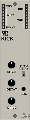
KICK
Analogue drum machine style kick (bass) drum
Module power consumption: 3 mA
Inputs
- Trig - use a pulse to activate the module sound, usually via one of the divider modules, or the Topograf module.
- Mult - a passive signal mixing/splitting capability on several AE modules, no control of signal levels within the module.
- Bus Gate - +5V with key on from an external keyboard over midi via the master module.
Outputs
- Out (3) - signal out.
- Mult - passive signal mixing/splitting, no control of signal levels within the module.
Controls
- Pitch - sets basic pitch of sound
- Decay - sets how long it takes the sound to stop after triggering.
- Drive - more drive adds roughness/buzz and volume.
- Pitch Decay Switch - The Decay can also cause the pitch to drop as well as volume. 1980's Simmons drums...
- Trig - direct, manual triggering of module - very useful.
Patch Suggestions
The Kick module doesn't go very low in Pitch for modern tastes, going through one of the filters can fix this - the Nyle Filter is recommended.
The Lo Fi delay can be fun...
2AUTO
This is a touch sensative knob movement recorder which generates CVs. The signal can be live, single trigger or looped amongst other permutations. There are 2 independent recorders.
View Kyaa's Shop Page - currently on pre-orders for the next production batch.
Module power consumption:
Inputs
- Trig A - A trigger signal activates the recorded CV of circuit A,unless in loop mode.
- Trig B - A trigger signal activates the recorded CV of circuit A, unless in loop mode.
- Clock in - unlabeled but the arrow to the bus/ext switch gives it away! This input does not need to be used if you are using a midi clock (e.g. drum machine, sequencer) into the master module.
Outputs
- A (3) - Output from knob A's noodlings....
- Trig A - The gate signal from input A is duplicated here, or a trigger gate will be generated at the begininng of each loop.
- B (3) - Output from knob B's noodlings....
- Trig B - The gate signal from input B is duplicated here, or a trigger gate will be generated at the begininng of each loop.
Controls
- EXT/Bus - This switch sets where the 2Auto uses the bus clock (usually derived from the midi clock input into the master module) or an signal plugged into the socket at the other end of the arrow.
There are 2 sets of controls; one for the A section and one for the B section. The controls are the same for each, as listed below.
The knob whose movement is used/recorded to set the CV. You start recording by touching the knob.
Switches -
- SYNC - If Sync is on, the 2Auto will activate the loop in time with the clock signal being recieved at the clock in input.
- Loop - this turns on/off loop mode. In loop mode the 2Auto becomes, in effect, a customisable LFO where any pattern can be repeated upto a length of 30 seconds. When not in loop mode it is like a (very) complex shape envelope generator, again up to 30 seconds long.
- Lock - When this switch is on the recorded pattern is protected, and touching the knob does not erase the recording, this is excellent for use live in particular so you have less accidents...
Patch Suggestions.
-
There is an active thread for this module on the forum:- https://forum.aemodular.com/thread/2083/2auto
-
This module can be used anywhere where you would use an LFO or an Envelope Generator - excellent for controlling filter cut off as you can be as wild or as subtle as you like very easily, without needing further processing through attentuentors etc.
-
The same applies for other areas where a modicum/high degree of control of the CV is required, the wave modulation on the Wavetables module is a great example. In this example you can create interesting timbral changes without the use of a filter.
-
You can make a live/controlled stereo panner in conjunction with the Mixconsole module by panning 2 channels hard left and right ands then controlling their levels with the 2Auto. There are several options here, using section A on one channels and section B on the other is the easiest, but you could use the 2CVTool for instance to provide the "reverse" signal to supply the other channel from one section's output.
-
It can be a fun sequencer in one shot or loop mode, put the output through the Quantizer module to be tuneful (if you want to be!).
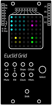
Euclid Grid
This is a 4 channel Euclidean step sequencer with a colourful animated display and hands on performance controls.
| sequence | display colour |
|---|---|
| A | Cyan |
| B | Magenta |
| C | Yellow |
| D | Green |
Inputs
- Clk - External clock input
- Rst - When you apply a high level signal it pauses all signals for as long as the level is high
- A | B | C | D - Applying a high level signal to any of these inputs will activate the additional fill steps for the respective sequence for as long as the signal level is high
Outputs
- B. Clk - On the left hand side - outputs the bus MIDI clock signal
- B. Stop - On the left hand side - outputs the bus MIDI stop signal
- A | B | C | D - On the right hand side - (x2 each), outputs the triggers for each respective sequence
- "Column" Sockets (x8) - above the display. These will produce a trigger when a step of any sequence is in that output's column on the display, as marked by the lines below the sockets.
Controls
In this section the use of the encoder, (select knob) is designated by the ↻ symbol.
- Select knob. used to select the active sequence, the one the controls will affect. The selected sequence will flash until another button is pressed, or a few moments have passed before coming active.
How to move a sequence.
- ↔ + ↻ Moves the selected sequence left or right.
- ↕ + ↻ Moves the selected sequence up or down.
This can be for convenience, but moving the sequence side to side will affect the triggers produced by the sockets above the display....
How to modify a sequence.
- Steps + ↻ Changes the number of steps in the active sequence.
- Offset + ↻ Nudges the steps in the active sequence to the left or right.
- ↔ + Shift ↻ Changes the width of the sequence.
- ↕ + Shift ↻ Changes the height of the sequence.
- Steps + Shift ↻ Changes the length of the sequence.
- Shift ↻ Changes the step mode of the sequence,
Step modes determine how the sequence plays. These are the available modes:-
- Horizontal
- Horizontal Reverse
- Horizontal PingPong
- Vertical
- Random
How to perform a sequence.
- Mute Stops the active sequence from playing. Can be a toggle switch, or muted as the button is held down.
- Fill Adds additional notes to the active sequence. Can be a toggle switch, or the fill plays whilst the button is held down. If you want to trigger fills on the other sequences, you need to use the lettered inputs; in this way it is possible to have fills triggered on all 4 sequences simultaneously. The Gate output on the JOYSTICK module could be used, or the 6MUTE controlling +5V CVs from, for example, the 2ATTCV module.
What is a Fill? On Euclid Grid, a Fill is a secondary Euclidean sequence that is overlaid over the first. They are represented with the color white.
How to modify Fill parameters. Fills can be modified much like normal sequences via the following methods.
- Fill + ↻ Changes the number of steps in the selected fill.
- Fill + Steps + ↻ as per Fill + ↻.
- Fill + Offset + ↻ Nudges the steps in the selected fill to the left or right.
How to change the Internal clock.
- Clock Starts or stops the internal clock depending on state.
- Clock + ↻ Increases or decreases the tempo of the internal clock by 10.
- Clock + Shift ↻ Increases or decreases the tempo of the internal clock by 1.
All sequences will reset after three seconds of no clock being applied (internally or externally).
How to save and load a performance.
- Mem Loads the last saved state from memory.
- Mem + Shift Saves the current state to memory.
Patch Suggestions
Combining different sequences of different lengths can result in polymeter, (polyrhythms) especially odd and prime numbers (i.e. 5/8, 4/13). Highly recommended!
A Euclid sequence will always try to evenly space the triggers as much as possible, so X X X X o o o o o o o o o o o o would be impossible. If you make the right shape on the Grid display however, you can do this:-
X o o o X o o o X o o o X o o o is the sequence you would use, but display it as
- X o o o
- X o o o
- X o o o
- X o o o
and the key here is to then run the sequence in vertical mode. Variations on this idea are myriad....
The individual trigger outs can also be used to vary your sequence, by using an attenuator if needed to give you control over the amount. The 2ATTCV and 4ATTMIX give you the attenuation/ control required. Might also be good with the ADSR....
As this module can produce 4 independent patterns of triggers, plus the individual column outs, module like the LOGIC, 3VCSWITCH and OR2x4 may well be interesting...
Here is an introductory video by the 5th Volt...
and this one with some amazing patches towards the end by RSKT...
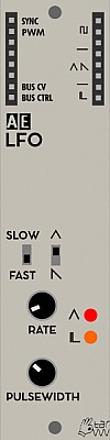
LFO
This module is discontinued, replaced by the 2LFO module
The low frequency oscillator (LFO) module generates modulation voltages mostly below the audio range.
Module power consumption: 3 mA
Inputs
- SYNC - resets the LFO waveform when a trigger pulse is received
- PWM - control voltage input for pulse width modulation of PULSE wave output
Outputs
- SQUARE - low frequency square wave with fixed width (half cycle)
- TRIANGLE / SAWTOOTH - low frequency triangle or sawtooth wave
- PULSE (L) - low frequency pulse where pulse length is set by the PULSEWIDTH knob
- BUS CV - control voltage signal from MIDI
- BUS CTRL - CTRL signal from MIDI (CH1 - CC20)
Controls
- RATE knob - frequency control
- PULSEWIDTH knob - set the pulse width of the output
- SLOW / FAST switch - switch between two frequency ranges
- TRIANGLE / SAWTOOTH switch - choose the waveform of the TRIANGLE / SAWTOOTH output
- TRIANGLE LED - visual reference for the TRIANGLE / SAWTOOTH output
- PULSE LED - visual reference for the PULSE output
Patch Suggestions
LFO can be used for modulating other oscillators (FM), VCAs (AM), filters, etc. But may also be used as clock or gate.
Patching two unsynched LFOs through a logic module then to a sequencer creates interesting uneven rhythms. Changing their pulsewidth creates new rhythms.
Combined LFOs connected to CV switches or a multiplexer results in a simple and versatile trigger sequencer.
When cranked up to audio range (RANGE knob all the way to the right in FAST mode) may be used as audio oscillator.
This video by Synths & Things explains the ins and outs of this module really well: https://youtu.be/T87dYf1YIeU
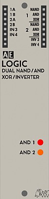
Logic
The LOGIC module contains two separate logic operators and two signal inverters.
Each operator combines two inputs by different logical rules (AND, NAND, XOR). This can be used
- either for operations on trigger / gate signals (let gate signals pass depending on other signals, invert them depending on the other input etc.)
- or for audio signals, where you get ringmodulator-like sounds when feeding two different oscillator frequencies.
Inputs
- 1A - First signal input for logic operator 1
- 1B - Second signal input for logic operator 1
- 2A - First signal input for logic operator 2
- 2B - Second signal input for logic operator 2
- IN3 - Signal to be inverted
- IN4 - Signal to be inverted
Outputs
The outputs are grouped in two identical groups marked with number 1 and 2 for each individual LOGIC operator. We only describe the outputs of one group as they work exactly the same for the other group.
NAND - (Not AND) outputs a LOW signal when both input signals are HIGH. Otherwise outputs HIGH. This is the truth table:
| input A | input B | output |
|---|---|---|
| 0 | 0 | 1 |
| 0 | 1 | 1 |
| 1 | 0 | 1 |
| 1 | 1 | 1 |
- AND - outputs a HIGH signal when both input signals are HIGH. Otherwise, outputs LOW.
| input A | input B | output |
|---|---|---|
| 0 | 0 | 0 |
| 0 | 1 | 0 |
| 1 | 0 | 0 |
| 1 | 1 | 1 |
- XOR - (Exclusive OR) outputs a HIGH signal when either input signal is HIGH but not when both are HIGH or LOW.
| input A | input B | output |
|---|---|---|
| 0 | 0 | 0 |
| 0 | 1 | 1 |
| 1 | 0 | 1 |
| 1 | 1 | 0 |
- INV3 - Inverts the signal of IN3 input. If IN3 is HIGH, it outputs LOW. If IN3 is LOW, it outputs HIGH.
- INV4 - Inverts the signal of IN4 input. If IN4 is HIGH, it outputs LOW. If IN4 is LOW, it outputs HIGH.
Display
- AND 1 - Visual reference for the first logic gate AND output. When AND output is HIGH, the LED turns on. When the AND output is LOW, the LED turns of.
- AND 2 - Visual reference for the second logic gate AND output. When AND output is HIGH, the LED turns on. When the AND output is LOW, the LED turns of.
Patch Suggestions
- The very basic patch is to connect one Pulse LFO into 1A and another one into 1B. Then connect any of the outputs of group 1 to the a VCA's CV input.
- Patching an LFO to input 1A and an audio signal to 1B (or vice versa), converts the logic gate into a signal gate (through AND or NAND outputs), letting the audio signal through when the LFO is HIGH and cutting it when LOW.
- For ringmodulator-like sounds, connect one audio rate oscillator to 1A and another one to 1B. Try different wave shapes. Square and pulse work best but other shapes give interesting glitchy effects. You can make serious sounds by patching two square waves into the A inputs of the XOR, then two square waves into the B inputs. Take the outputs of the two XOR and patch them into the A and B input of a third XOR an then listen to the output while slowly adjusting the frequency of the oscillators.
- Patch in square/pulse Waves into the logic module and listen to the XOR out for incredibly rich and morphing Waves. Tuning the squares and changing PWM generates an Endless amount of timbres. The first XOR out can be recombined with one of the square Waves in the other logic input for another XOR out.
- Do the same thing but with a stereo output, e.g. send the XOR to the left ear and OR to the right ear.
- Or send the XOR into a filter and use the AND to modulate the cutoff frequency.
- Basically just use it like a VCO, by processing other VCOs.
- You can create new truth tables (LOGIC gate operators or logic rules) by patching the output of one group to one of the inputs of the other group or to the inverters. For example, connecting XOR1 to IN3 would result in INV3 outputing HIGH when both signals are HIGH or LOW, but not when one of them is HIGH and the other one LOW, resulting in a XNOR gate (Exclusive Not OR gate). See the truth table and notice that it's the exact opposite of the XOR truth table.
XNOR
| input A | input B | output |
|---|---|---|
| 0 | 0 | 1 |
| 0 | 1 | 0 |
| 1 | 0 | 0 |
| 1 | 1 | 1 |
Combine a number of these modules and you get a crazy GATE / TRIGGER sequencer.
You also may find this link useful. https://doudoroff.com/logic/
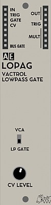
LOPAG (VACTROL LOW PASS GATE)
This is a fairly subtle module filter wise, and certainly shouldn't be a first filter purchase as there is no direct control of the filter itself other than on/off.
This doesn't mean it isn't useful however....
Module power consumption: 1 mA
Inputs
- IN - the audio signal input. This module will not make any sound without this.
- TRIG - A +5V pulse will activate a short opening of the gate.
- GATE - The module will sound for the length of the +5V pulse provided, use the PWM output of an LFO module and then you can adjust this time on that module.
- CV - The module will sound to the volume (voltage) and length of the signal provided, e.g. an ENV module will let you do full attack, decay, sustain and release shaping.
- BUS GATE - This is actually an output generated from the Master module from Midi, it will be zero or +5V when a relevant key is pressed on a connected keyboard.
Outputs
also see Bus Gate above.
- OUT (x3) - the audio signal output.
- TRIG - the trigger from trig in is output here,
- MULT - a passive mixer/splitter completely separate to the module circuits.
Controls
- VCA/LP GATE switch - this turns the filter circuit on or off. Useful for seeing what is actually being done to the sound, or if you are short of VCAs.
- CV LEVEL knob - This controls to amount the CV input affects the volume of the sound, too far anticlockwise and there will be no sound unless one of the other inputs is used as well.
Patch Suggestions
It can be used as a straight VCA triggered by the gate, CV and/or trig inputs in any combination or singly; this can be very useful for polyrhythmic effects. One more CV/trigger input than the regular AE VCAs. This works in either LP or VCA mode.
It is good for adding "Punch" to percussive sounds, especially the AE KICK module.
It can save using a filter and VCA module if it does what you want to the sound, with less patching and CV/ triggers then needed also.
The classic running a held chord, (SOLINA!}, through a gate triggered in time to the drum pattern is very good with this module, in either mode. The Gate input is really useful for this as you can then adjust how long the chord is heard for - if your trigger is too short, put through a ENV module and use that output into the gate or the CV input on this module.
This module does not have CV control of resonance, but it can be created by putting one of the outputs through a VCA whose level is controlled by the CV modulation source (e.g. LFO or envelope), then feeding the VCA output back into this module - you will need a mixer module, or use a mult if necessary as there is only one input. Be aware you will not be able to adjust the frequency like on a regular filter but it can still be useful/ interesting.... Process the sound further before feeding it to the VCA?
Sound Examples
AE Modular filter comparison: https://www.youtube.com/watch?v=ZY9VkSyMrik
Le Module.
The new (2023) module is a chord generator. It is available via M4vrick on the AE Modular forum, you can read some informations about its development on the forum: https://forum.aemodular.com/thread/2593/french-home-vco-module-le
Inputs
- Frequency - affects the pitch of the sound
- Table - changes the chords, sometimes the harmonics of the sound.
- Wave - affects the harmonics and/or chords in the sound.
Outputs
Bottom left
- Bus Gate - on early modules this is actually the bus CV derived from the midi input on the master module, usually for the pitch.
- Bus CV - on early modules this is actually the bus CV derived from the midi input on the master module, usually key on/off.
Top Right
- Out 1 - Main output.
- Out 2 - duplicate output, quite useful for using a different filter &/or FX on.
- Mult - a passive splitter/mixer not connected with the module circuitry.
Controls
- Frequency - sets the pitch of the sound, affected by the CV input above.
- Table - sets the chord and/or harmonics of the sound, affected by the CV input above .
- Wave - changes the chord/harmonics within the range set by the table knob, affected by the CV input above.
Patch Suggestions
Excellent video by RSKT
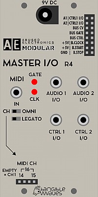
MASTER
This Master module description is for the one supplied until December 2019, the replacement is the same, except for having an extra switch to change the midi channel from 1 or Omni to some of the others available.
The Master module has 2 jobs, bringing power to the AE Modular, and being a Midi/CV converter. It is possible to have an AE modular without a Master, you just need a suitable 5V supply (the Master module converts the 9V supplied to 5V for internal use). There is a 1 unit module in the Tangible Waves shop for precisely this purpose.
https://www.tangiblewaves.com/store/p85/POWER.html
There are various synths and keyboards/ sequencers available with Gate/CV outs but you will need to keep an eye on the maximum voltage they send; the AE modular will be damaged if provided with more than 5 volts, (or negative voltage). This problem can be avoided by use of the 4 I/O module, or a Midi synth/keyboard/ sequencer and the Master module.
NOTE: When connecting MIDI to the Master module, be sure to use the adapter from tangible waves or a different type 'B' plug (more info on the different types of MIDI-TRS converters here).
The Master module also supplies the various bus CVs available on many modules, all are derived from the Midi information received. These bus CVs mean a lot less patch cables are needed in many cases.
The descriptions here are for the current Master module, the original Kickstarter systems had a more primitive Master module which ideally needs to be replaced by this one.
Module power consumption: 30 mA
Inputs
Anything marked I/O can be an input or output.
9V input for PSU, (provided with starter systems, or available in the Tangible Waves shop).
3.5mm Minijacks.
- Midi - Needs a Midi breakout cable (provided with starter systems, or available in the Tangible Waves shop). The TRS MIDI is of type B.
- Audio 1 I/O - This socket connects with the AE patchbay sockets labelled A1 listed below.
- Audio 2 I/O - This socket connects with the AE patchbay socket labelled A2 listed below.
- CTRL 1 I/O - This socket connects with the AE patchbay sockets labelled 1 listed below.
- CRTL 2 I/O - This socket connects with the AE patchbay socket labelled 2 listed below
The difference between the audio and Ctrl inputs are the latter is meant for CVs, the former is the usual connection for your AE Modular to the external mixer/sound system etc.
AE Patchbay
- A1/ CTRL 1 I/O - the left socket is connect to the audio 1 I/O listed above. The right socket is connected to the Crtl 1 socket listed above.
- A2/ CTRL 2 I/O - the left socket is connect to the audio 2 I/O listed above. The right socket is connected to the Crtl 2 socket listed above.
Outputs
- Bus CV (2) - a CV derived from the midi note number from attached device.
- Bus Gate (2) - +5 volts when a key is pressed/held on attached midi device.
- Bus CTRL (2) - a CV controlled by Midi CC20
- +5V (2) - what it says!
- B. Clock - the midi clock (if provided by attached device)
- B. Start - +5V pulse when start button is pressed on attached Midi device.
- GND - zero volts, can be useful to control hum in certain circumstances.
- B. Stop - +5V pulse when stop button is pressed on attached Midi device.
Also see items marked I/O above, as can be inputs or outputs.
Although you can use the above Bus outputs to feed a signal into the relevant buss, it may not be 100% reliable, and definitely will not be if you mix it with incoming midi - but you won't break anything and it could be interesting!
Controls
None.
Eurorack Power Supply
The Master module also can be used to supply AE modules and interface to eurorack modules when used with an AE Modular eurorack adapter frame. Eurorack adapter frames are available with 8, 12 or 16 units.
AE Modular Eurorack Adapterframe 8U
An eight units eurorack adapter with a Master module about to be put in:

With the adapterframe comes an eurorack power-cable for the Master module:
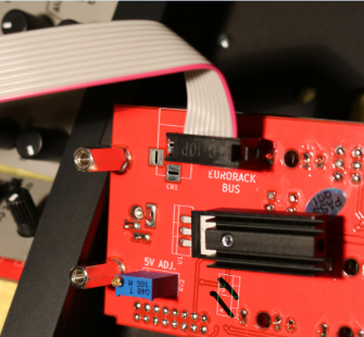
The 10-pin connector plugs to the Master module, red cable facing downwards, the other connector plugs into one of your Eurorack bus sockets.
Patch Suggestions
The most obvious use of the Master module is the midi (bus) CV being used to control the pitch of the oscillators. The Bus CV needs to go to the CV in on your VCO, this can be done on the Oscillator module itself rather than a patch lead trailing across from the Master module.
For the starter systems, the Master module will be your audio out, feeding the output from the last module in your patch to the AE patchbay A1 or A2, then the equivalent mini jack socket having the lead going to your external equipment. the 4 I/O module can do the same job which can make patching tidier.
The Bus clock, start and stop can be used to control the AE Modular's sequencer modules but, again, this can often be patched on the sequencer modules themselves rather than from the Master module. If using the Midi clock to control tempo you will need a divider module to reduce the number of pulses per quarter note.
The use of a Midi controller such as the Arturia Keystep, Beatstep (pro) or synth with sequencer built in is highly recommended to control the AE Modular as the Master module provides a lot of options and the system is geared to work this really well with, for instance, the bus CVs.
Connecting MIDI from a computer
You can also connect MIDI from a PC/Mac so that you can sequence the AE Modular from a DAW (Digital Audio Workstation) like Ableton or Reaper. For this to work you need to purchase a converter cable that converts USB to MIDI Din. Here is an example:
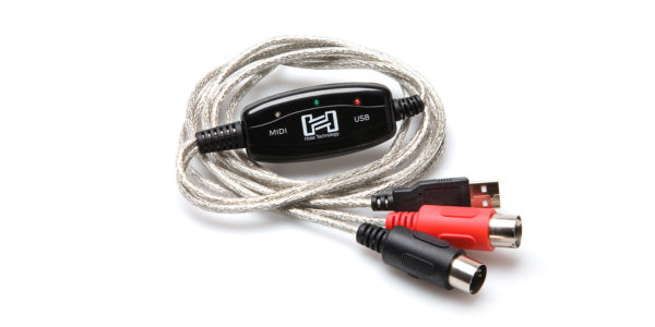
https://hosatech.com/products/data/midi-interfaces/usm-422/
There are many variations of these cables, some are much cheaper than the one above. But buyer beware, cheap cables can sometimes cause "jitter" which may lead to note skipping and stuck notes.
This video shows a very basic patch that makes use of the MIDI connectivity of the Master module: https://youtu.be/Z1zWIMh0a_s
This very short video shows how you can sync and connect a Korg Volca with the AE Modular via the Audio and CTRL inputs on the MASTER module: https://youtu.be/VB3sRZlU1wE

METER
This is a multi-functional module for visualizing and measuring signals.
Inputs
- IN - Signal to be displayed/analysed
- Mult - this can be a simple mixer (only really worth it for CVs) or a way of splitting a signal to several outputs, e.g. a trigger for Envelopes for the filter and VCA at the same time. You can plug anything (in/out) into any mult socket.,
Outputs
-
+5V - A steady 5 volt signal.
-
B.CV - The bus voltage derived from the midi note number via the Master module. The higher the note number the higher the voltage
-
Midi Out - Midi CV from bus via Master module, defaults to A for tuning purposes. See Oscillator calibration later.
Controls
- Timebase - this lets you zoom in to see a waveform (or part of), or see several waveforms at once.
- Mode - selects modes as below
There are 5 different display modes for the input signal, and a 6th mode for calibrating oscillators using the midi out socket on this module.
The 5 modes are
-
oscilloscope AC - for displaying alternating current signals
-
oscilloscope DC - for displaying direct current signals
-
spectrum analyzer - display the frequency spectrum of the input signal, lowest frequency to left, higher to right, the taller the graph spike the louder that frequency is.
-
voltmeter displays the voltage of input signals
-
frequency meter displays the frequency of the input signal; displayed as hertz and as musical note with +/- 100 cent difference. (The frequency of the root "A" can be adjusted) how
-
Threshold - this sets the level at which the display will start displaying the signal.
-
AC Mult switch - this is usually set on x1; this is the module using the signal as it is. the x2.5 position increases the height of the display to increase visuals and can help with fine tuning the signal.
Display
The reason for buying this module!
Patch Suggestions
Calibration of an OSC This module can be used for oscillator calibration. Take the Midi out CV to your oscillator CV in, Pick a simple waveform out and put that into the Meter module in.
For calibrating the VCO with the METER module, you use best the square wave output with a medium pulse width of the VCO, connected to the METER input. Additionally, you connect:
- BUS-CV with CV in on the VCO, and
- via a stereo minijack cable the MIDI out from METER with MIDI IN on the MASTER
Put the Meter module in Osc. Calib mode and follow the instructions on the screen.
Other uses This module is great for adding activity for a video, or low light level playing!
It can be useful for helping set the gate length on triggers from LFOs etc.

MIXCON JACK OUT
This module adds the convenience of plugging 1/4 inch (6.5mm) cables straight into the AE Modular without having to use any adapter cables. It is not a freestanding design, it needs to MIXCONSOLE to work, and has to be mounted adjacent to that module where it connects via a short cable at the back.
Inputs
These are acquired from the Mixconsole, except...
- FX1 Return L - the level of this signal is controlled by the FX1 rtn lvl knob (on the Mixconsole).
- FX1 Return R - the level of this signal is controlled by the FX1 rtn lvl knob (ditto).
- FX2 Return L- the level of this signal is controlled by the FX2 rtn lvl knob (ditto).
- FX2 Return R- the level of this signal is controlled by the FX2 rtn lvl knob (ditto).
Outputs
- FX1 Send - Mono out controlled by the 4 FX1 send knobs (on the MIxconsole).
- FX2 Send - Mono out controlled by the 4 FX2 send knobs (ditto).
- Master L Left signal of the stereo mix, Main out of the Mixconsole.
- Master R Right signal of the stereo mix, Main out of the Mixconsole.
Patch Suggestions
This module is useful if you want to restrict the number of 3.5mm to 6.35mm cables you need to buy!
More seriously it means regular studio leads can be used which generally give better audio quality and, probably, more reliable connection. They also come in much longer lengths if needed....
If you are also adding the XLR outputs, ideally this module should be attached first, then the MIXCONXLR ...

MIXCONSOLE
The MIXCONSOLE is a "proper" mixer with FX sends, and stereo out with AE and 3.5mm jack outputs. It comes with 4 channels but is infinitely expandable with the MIXCONSOLE - 3CH. Each channel has CV control of it's level available.
Module power consumption: 28mA
Inputs
- IN 1 - IN 4 - the signal in for each of the 4 channels.
- CV 1 - CV 4 - the CV input for each channel which works in conjunction with the same numbered level knob in that the knob controls the maximum amplitude of the channel, and when you feed in CV then you can change the amplitude from 0 up to what the knob allows.
On the right side, (usually outputs on the AE):
- FX1 Return L - the level of this signal is controlled by the FX1 rtn lvl knob
- FX1 Return R - the level of this signal is controlled by the FX1 rtn lvl knob
- FX2 Return L- the level of this signal is controlled by the FX2 rtn lvl knob
- FX2 Return R- the level of this signal is controlled by the FX2 rtn lvl knob
These could be utilised to input more signals into the mix as well, (not just FX)....
Outputs
- Main Out L - Left channel of the stereo mixed output.
- Main Out R - Right channel of the stereo mixed output.
- FX1 Send - Mono out controlled by the 4 FX1 send knobs. For patching within AE.
- FX2 Send - Mono out controlled by the 4 FX2 send knobs. For patching within AE.
3.5mm sockets:
- FX1 Send - duplicates the above. Mono. Great for patching in external FX.
- FX2 Send - duplicates the above. Mono. Great for patching in external FX.
- FX1 Return - Stereo, level of this signal controlled by the FX1 rtn lvl knob
- FX2 Return - Stereo, level of this signal controlled by the FX2 rtn lvl knob
- Main L - Left signal of Stereo mix.
- Main R - Right signal of Stereo mix.
- Main Out Stereo - Left and right signals of Stereo mix.
3.5mm to 6.35mm leads are readily available to link to most studio gear, but some others also use 3.5mm sockets.
Important to note that the FX Send 3.5mm output is really only MONO. So if you put a stereo plug into it, you will receive the sound only on the left side of the stereo signal! So if you send this to an effects processor which expects a proper stereo input (eg. the Korg NTS-1) you will only get the effect on one channel, which can be frustrating if you don't expect it.
You can also add these modules for more output options:
- https://wiki.aemodular.com/pmwiki.php/AeManual/MIXCONJACKOUT
- https://wiki.aemodular.com/pmwiki.php/AeManual/MIXCONXLROUT
Controls
Each channel has 4 knobs with the same function, (Channel number is by the level knob):-
- FX 1 Send - controls the amount of signal sent to FX1 send output.
- FX 2 Send - controls the amount of signal sent to FX2 send output.
- Pan - set where in the stereo field that channel is played, from fully Left to fully right.
- Level - controls the amount of signal in the Mix L/R outputs.
Do bear in mind that the amount of signal sent to the FXs (and their return level) will also affect the apparent loudness of the sound as well as the level control.
- FX 1 rtn lvl - controls the amount of signal from the FX 1 return inputs in the Main outputs
- FX 2 rtn lvl - controls the amount of signal from the FX 2 return inputs in the Main outputs
- Main Level - Sets the volume of the Main outputs
Display
The LEDs give you an idea of the levels of the mixed signals going to the main output. Green is good, a little bit of yellow is best. Unless you want distortion you generally want to avoid the red LEDs being lit a lot...
Patch Suggestions
First up, you can now save on VCAs with this module. Whenever you had a VCA as the last piece in the chain before going to the mixer, you can now do the same with directly sending ENV or LFO CV to the CV input of the respective channel.
Mono FX sends are very common on mixers, so ideally you need an FX unit with mono in/ stereo out (or can be configured that way). Within the AE, the MULTIFX is perfect to connect with this module.
Some people like the main sound on 1 side of stereo, and the FX'ed signal on the other - this is easy to do on the Mixconsole but just using 1 of the FX return sockets.
The Stereo 3.5mm FX returns can be rather handy for bringing in external signals, the best example is the Korg Volcas where they have a stereo 3.5mm out.
The Mixconsole is great for doing sub-mixing of oscillator outputs where you want them to vary over time; each oscillator output goes to a different channel and then the levels can be controlled by LFOs, ENVs and even the JOYSTICK module.
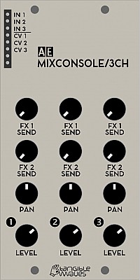
mixconsole3ch
MIXCONSOLE/3CH
This module is not a freestanding design, it needs the MIXCONSOLE to work and attaches to it via a special flat cable at the back.
The great thing is that you can chain as many of the 3CH modules as you like so could make a 28 channel mixer if you wanted!
(28 is the maximum number because all these modules have to be situated directly next to each other and on the widest available case you can only fit 8x 3CH and one MIXCONSOLE module in one row.)
Module power consumption: 15mA
Inputs
- IN 1 - IN 3 - the signal in for each of the 3 channels.
- CV 1 - CV 3 - the CV input for each channel which works in conjunction with the same numbered level knob.
Controls
Each channel has 4 knobs with the same function, (Channel number is by the level knob):-
- FX 1 Send - controls the amount of signal sent to FX1 send output.
- FX 2 Send - controls the amount of signal sent to FX2 send output.
- Pan - set where in the stereo field that channel is played, from fully left to fully right.
- Level - controls the amount of signal in the Mix L/R outputs.
Do bear in mind that the amount of signal sent to the FXs (and their return level) will also affect the apparent loudness of the sound as well as the level control.
Patch Suggestions
Please see the MIXCONSOLE page for further reading.

MIXCON XLR OUT
This module adds two mono, balanced XLR jacks to the Mixconsole. It is not a freestanding design, it needs to MIXCONSOLE to work, and has to be mounted adjacent to that module and connects via a short cable at the back.
Inputs
These are acquired from the Mixconsole.
Outputs
- Master L/ Bal Left signal of the stereo mix, Main out of the Mixconsole.
- Master R/ Bal Right signal of the stereo mix, Main out of the Mixconsole.
Patch Suggestions
This module enables the AE to be patched into professional audio equipment. It is also worth considering if you are having problems with hum or ground loops when connecting your AE.
If you are also adding the MIXCONJACKOUT module, that module should be connected to the Mixconsole first. This module can be attached to either.
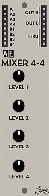
MIXER 4-4
A 4 input, 1 output audio mono mixer (i.e. not stereo), with individual channel knob for levels. There is also a 4 channel mixer (B1 – B4) without control which can be used for mixing CVs.
Module power consumption: 5 mA
Inputs
- A1 - Channel 1 of the A mixer.
- A2 - Channel 2 of the A mixer.
- A3 - Channel 3 of the A mixer.
- A4 - Channel 4 of the A mixer.
- B1 - B4 - 4 inputs for the mixer without any level control within the module.
Outputs
- A (2x) - Output of Mixer A.
- B (2x) - Output of mixer B
- Mult - labelled Thru on some modules. A passive mixer/ splitter not connected to the module circuits.
Controls
- Level 1 knob - The level of input A1 in output A.
- Level 2 knob - The level of input A2 in output A.
- Level 3 knob - The level of input A3 in output A.
- Level 4 knob - The level of input A4 in output A.
Patch Suggestions
The most obvious use is to patch the oscillator(s) and noise module to the Mixer 4/4 to have a complex sound before it even gets to the Filter etc.
If you want a "chiff" of white noise at the beginning of the sound, put the Noise thru a VCA controlled by an Envelope before it goes to the mixer. The same applies if you want a higher pitched oscillator to fade in over a held note, use use a VCA and an envelope with a slow attack before the mixer and voila!
The B mixer is the best way of combining CVs, it can be done via the Mult/Thru on various modules, but that is less reliable. An LFO and Envelope combined before going to the filter can be really useful. Combining CVs is helpful for any module that only has one CV input, or where you want more than one sort of modulation on a specific item, e.g. Filter cutoff Frequency.
Notes
Mixer Module Comparison Table August 22.
If the inputs or outputs say 1, this is mono. If the inputs or outputs say 2, this is stereo. If there is a number in brackets after, that is the quantity of that type; e.g. the 4ATTMIX has 4 of the same mono output.
Mono mixers are usually meant for CVs, and stereo mixers are usually meant for audio, but feel free to experiment! Several of the modules have audio/CV switches for improved sound quality.
Model
Cost (3/22)
Module Space
Inputs
Outputs
FX Send
FX Return
Level Meter
Headphone
Built in FX
Wiki Page
4ATTMIX
€29.00
1
4
1 (x4)
N
N
N
N
N
4ATTMIXFADER
€36.00
2
4
1 (x4)
N
N
N
N
N
Compact Mixer
€118.00
6
10
2
2
2(x2)
Y
Y
N
Dronx
€75.00
4
6
1(x3)
2
2
N
N
Y
Mixconsole
€80.00
4
4
2
2
2(x2)
Y
N
N
Mixer 4 4
€22.00
1
4
1(x2)
N
N
N
N
N
Polamix
€31.00
1
3
1(x2)
N
N
N
N
N
XMIX
€32.00
1
3
1(x2)
N
N
N
N
N
µ2Mix
€28.00
1/3
4
1(x2)
N
N
N
N
N
MM33
£60.00
2
3
3(x2)
N
N
N
N
N
- The 4 Attmix and 4AttMixFader are the same module electronically. The faders are really useful for audio mixing.
- The Compact Mixer has all connections available as AE or 3.5mm sockets.
- The Dronx also has distortion & a tone control for the overall mix.
- The Mixconsole has CV control of channel levels, (only one in AE), and is infinitely expandable with accessories, please see the Wiki page.
- The Mixer 4 4 has another ("B") mixer built in, which is 4 mono inputs (no control over level) to 2 mono outputs, great for CV mixing.
- The Polamix has an offset knob as it designed for CV mixing primarily.
- The Xmix has 3 other mixers built into the module, with little control over the input levels so mostly for CV mixing. These are a 4 to1 mixer, and 2 mixers that can be 4 to 1 or a 8 to 1 with 4 of the inputs attenuated at a fixed level.
- The µ2Mix has another ("B") mixer built in, which is 4 mono inputs (no control over level) to 2 mono outputs, great for CV mixing. On the main mixer, there are level controls for 3 inputs only. This module has to be mounted in the uBase module.
- The MM33 is a matrix mixer, i.e. any of the 3 inputs can go to any of the 3 outputs, their levels set by the knobs on the front panel. Very useful for CV modulation matrix, and for more complex audio patching.
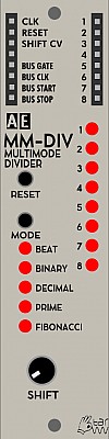
MM-DIV
A multi-mode divider for clock and audio signals.
It can be used either for dividing clock signals (e.g. from an LFO, BEATDIVIDER) for rhythmical purposes but also for audio signals - in this case you get subharmonics / lower octaves squarewaves at the outputs, which can be mixed or used separately.
The module has eight outputs which - depending on the selected division mode - provide different division factors of the input signal:
- Beat: musical/rhythmical clocks are generated as 1/1, 1/2, 1/4... 1/16 and triplets
- Binary: the outputs work as binary counter (same as the predecessor module DIVIDER)
- Decimal: The outputs have decimal divisions of the input, meaning half, third, quarter, fifth... of the input clock
- Prime: The outputs use the prime numbers as division factors
- Fibonacci: The outputs use the numbers of the fibonacci row as division factors
Module power consumption: 10 mA
Inputs
- CLK - clock input either triggers,square waves or audio signals
- RESET - CV gate or trigger to reset all output signals; in case of audio signals this can get quite unique, ringmodulator-like sounds.
- SHIFT - CV gate or trigger to shift/rotate the outputs; usually, the fastest output is on output 1, but with shift the entire output pattern is shifted so the fastest output can be set to any position 1...8.
Outputs
- 1..8 - 8 trigger out puts for the different clock divisions
- BUS GATE - MIDI Gate signal from the internal bus
- BUS CLK - The MIDI clock signal from the internal bus. Please note that the actual clock resolution depends on your MIDI clock source. The MIDI standard is 24ppqn (Pulses per Quarter Note)
- BUS START - sends a trigger when the MIDI start message is sent from a connected MIDI device
- BUS STOP - sends a trigger when the MIDI stop message is sent from a connected MIDI device
LED Indicators
- 1..8 - each of the 8 LEDs will light up when the associated trigger is active
- MODE - LED lights to the left of the selected division mode
Controls
- RESET - resets all output signals; in case of audio signals this can get quite unique, ringmodulator-like sounds.
- MODE - select the division mode.
- SHIFT - shifts/rotates the outputs; usually, the fastest output is on output 1, but with shift the entire output pattern is shifted so the fastest output can be set to any position 1...8.
Patch Suggestions
A clock divider can be used in many different ways. The most common use is to use it for rhythmical applications to trigger percussive sounds or advance the clock of a step sequencer. The different division modes can lead to interesting and uncommon rhythmical patterns. Using the shift knob, the pattern can be varied for dramatic effect.
The MM-DIV also accepts input in audio range. If you patch in a saw or triangle wave from an oscillator you can get sub oscillators out of the various outputs.
Here is a very quick demonstration by The 5th Volt on how to use the rotating patterns to play with drum sequences:

MODULATORS
MODULATORS is a multifunctional 1U module. It is designed especially with very small AE systems in mind.
It includes a simple EG, an LFO, a random CV generator and a VCA.
Module power consumption: 13 mA
Inputs
- ENV GT - The trigger input for the Envelope section.
- VCA IN - For the audio/CV that you want to control with the VCA
- VCA MOD - For the CV which controls the level of the VCA output.
- LFO PWM - CV input to change the shape of the LFO waveform, this could affect gate time (triggering envelopes), complexity of filter modulation amongst many other things.
- LFO SYNC - a CV pulse here will reset the LFO waveform to the beginning of the cycle; this is most useful where you want the sound to be the same for each key press/sequencer note.
Outputs
- ENV (x2) - CV output from the envelope section
- VCA (x2) - Audio/CV output from the VCA
- LFO Triangle/sawtooth - output from the LFO for these wave shapes
- LFO Square/PWM - output from the LFO for these wave shapes.
- This means the LFO can modulate 2 things separately without the use of a MULT.
- RND (x2) - CV output from the random section
Controls
-
ENV | ATTACK (knob) - Controls how quickly the CV rises when triggered. Please note that, in trigger mode, a slow attack could mean the envelope will not "play"; this is usually when the knob is over the 8 o'cock position.
-
ENV | RELEASE (knob) - Controls how quickly the CV descends when the attack or sustain ends.
-
ENV | Gate/Trig (switch) - This switch means you can either have just the A/D envelope (great for percussion) or sustain as well. This means the CV stays high until the trigger stops, e.g. when the key is released on a keyboard.
-
LFO | RATE (knob) - This sets the frequency of the LFO
-
LFO | PW (knob) - This sets the waveshape around a squarewave, moving this knob whilst playing is the same as applying a CV to the LFO PWM input.
-
LFO | Triangle/Saw (switch) - This selects which waveform you would prefer at the LFO Triangle/sawtooth input.
-
RND | MODE (button) -
Press and release of this button will mean the random CV will change in sync with the LFO; this means, in effect, it can be triggered via the LFO Sync input. Be aware that PWM in particular can cause there to be no triggers, due to zero pulsewidth (so no rise from zero volts). There is a three second delay for this sync to take effect due to the following use:-
Press and release the button multiple times sets the tempo of the CV changes, the faster you tap.... The longest gap between presses is 3 seconds.
Press and hold this button
The LED in the random section will then flash. You select between the three modes by releasing the button when it is on the one you desire. The mode the random section is currently in is shown by the number of flashes.
- 1 flash Quantized - the CV is in a minor scale from 0 to 2 volts. Useful for Oscilator & SOLINA pitch
- 2 flashes Random (stepped) - CV between 0 and 4 volts.
- 3 flashes Smoothed - As random, but the voltage changes more slowly between CVs.
Patch Suggestions
If you want more than one input to the VCA, you will need to use a mixer module such as the 2ATTCV. You can use a MULT if necessary however.
If you want a smooth(er) transition between the CVs of the Random CV generator, this can be done with the SLEW/EDGE module.

MS 20 FILTER
This filter module is a variant of the Korg MS20 filter. With a switch it can be turned into either lowpass or highpass filter mode, but not both at the same time.
Module power consumption: 3 mA
Inputs
- IN H - this input is for higher level signals.
- IN L - this input adds some gain to give a higher signal level of the module circuitry, (i.e. low input signals).
- CV 1 - accepts CV control for cutoff frequency
- CV 2 - additional CV control for cutoff frequency
Outputs
- OUT - the output of the filtered signal
- MULT - an unbuffered multiple
- BUS CV - this sits below the input jacks on the left side and will output CV pitch from a connected MIDI device
- BUS CTRL - this sits below the input jacks on the left side and will output the MIDI control message from a connected MIDI device.
Controls
- FREQ Knob - cuttoff frequency
- CV 1 Knob - control voltage attenuator
- RESONANCE Knob - sets the amount of amplification of the frequencies on/around the cut off point.
- LP/HP Switch - filter type lowpass / highpass
Patch Suggestions
The filter can be used just like any other filter in the AE range, however it offers a very pronounced and beautiful resonance that goes quickly into self resonance. It is excellent for lead sounds and bass.
This module does not have CV control of resonance, but it can be created by putting one of the filter outputs through a VCA whose level is controlled by the CV modulation source (e.g. LFO or envelope), then feeding the VCA output back into the same filter - you may need a mixer module, or use a mult if necessary as the levels on the 2 inputs are different. Try the low input for the feed back from the VCA first....
The MS20 Filter is adept at producing bass/kick drum sounds. Use the self resonance with the cutoff tuned low to your desire. To boost the bottom end, feed in a Sine wave (WAVETABLES, VCO or FMOS), again tune to what you want. From the filter; a VCA with a short attack is needed; the LOPAG module is good as it can further enhance the sound. To enhance the initial "thump" put a very short envelope into the CV1 input, the amount of "thump" can then be controlled by the CV1 Knob. These Kick drums are worth sampling to free up your AE for other duties!
Sound Examples
AE Modular filter comparison:
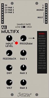
MULTIFX
A digital multi-FX unit which can be mono or stereo. There are 15 different programmes, each with 3 parameters that can be adjusted via the front panel knobs or CV. The programmes are listed on the display on the lower right hand side of the module, with the current selection being lit up.
Module power consumption: 64 mA
The video at the bottom of this page gives an excellent demo of what this module can do.
Inputs
- In - Signal for processing
- CV PAR 1 - CV which affects parameter 1 of the selected program in conjunction with the Par 1 knob.
- CV PAR 2 - CV which affects parameter 2 of the selected program in conjunction with the Par 2 knob.
- CV PAR 3 - CV which affects parameter 3 of the selected program in conjunction with the Par 3 knob.
Outputs
- L - left stereo output
- R - right stereo output
- MONO - mono output
- Mult (5) - a mixer/splitter separate to the main module electronics.
Controls
- Input Level knob - a useful attenuator/ boost for the signal being input to the module.
- Feedback Knob
- Dry Knob - sets the level of the original signal in the output.
- Wet Knob - sets the level of the effected sound in the output.
- Program Knob - selects the program as shown on the display on the right side of the module.
- Par 1 Knob - sets the amount of Parameter 1 for the selected program, usually the Pre delay/room size
- Par 2 Knob - sets the amount of Parameter 2 for the selected program, usually Reflections/repeats level
- Par 3 Knob - sets the amount of Parameter 3 for the selected program, usually Brightness/LPF cut off.
Effects Parameters
Program
Param 1
Param 2
Param 3
REVERB 1
Reverb time
High Filter
Low Filter
REVERB 2
Reverb time
High Filter
Low Filter
DEEP SPACE
Reverb time
Delay Time
High Filter
RESOVERB
Reverb time
Resonance frequency
Resonance feedback
SHIMMER
Shimmer
Shimmer feedback
Reverb time
PINGPONG
Delay time
Feedback
HighFilter
DUAL DLY
Delay Time Left
Delay Time Right
Feedback
DELAY+REV
Delay time
Feedback
Reverb mix
FLANGER
Reverb mix
Flanger Rate
Flanger mix
CHORUS
Reverb mix
Chorus Rate
Chorus mix
PITCH SH
Pitch +/- 4 semitones
PITCH DLY
Pitch Shift
Delay time
Delay mix
TREM REV
Reverb mix
Tremolo rate
Tremolo mix
GLITCH DLY
Delay time
Feedback/Alias
Pitch shift
RING CRSH
OSC Pitch
Crusher mix
Reverb mix
Patch Suggestions
This module is useful to create a stereo output from the AE modular, and can be sent out via the 2 I/Os on the Master module, or 2 of the 4 I/O module routes.
The reverbs and shimmer are excellent for drones/pads etc.
It can be used in conjunction with the Lo-fi delay to get echo type sounds with other FX, usually reverb.
The Mono output can be excellent to feed back into the AE modular to process the sound further, e.g. a filter on a reverb'ed lead sound can be really good. Do watch for causing feedback within the AE modular.
A slow attack envelope can increase one or more of the parameters which, usually, increases the level of the FX but always changes it. This can be really interesting.
This video by TheTuesdayNightMachines is a great demo of the different modes and effects of this module https://youtu.be/TW_Qw_0zdlM
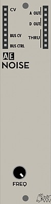
NOISE
The NOISE module generates ... yes ... noise!
There are three types of noise in the module: analog, digital and crackle. See outputs below for details.
Inputs
- CV - control voltage input for RATE (see below)
Outputs
- A OUT (2x) - analog noise: a fluctuating voltage between about 1v and 4V
- D OUT - digital noise: a random changing 0V / 5V
- CR OUT - crackle noise: random triggers (on newer versions)
- MULT, labelled Thru on the picture here - passive signal splitter/multiplier
- BUS CV - MIDI pitch signal from the bus
- BUS CTRL - MIDI control signal from the bus (CH1 - CC20)
Controls
- RATE Knob - controls the color of the noise, which goes from almost white noise on A output and knob fully clockwise to a rather harsh and digital sound on D output and RATE counter-clockwise. It also controls the density of the crackle on CR output.
Patch Suggestions
A popular patch is to connect A OUT to a VCA (IN) controled by an envelope to get percusive sounds.
Use D OUT for harsher bit-crushed sounds.
Connecting CR OUT to S&H (TRIG1) and A OUT to S&H outputs random voltages at intervals set by the trig input on that module.
When used as audio, CR OUT gives a nice vinyl-like crackle sound.
If used through an attenuator (e.g. 2ATTCV) it can be nice as a random modulation source on things like filter cut off.
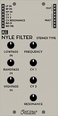
NYLE FILTER (STEINER TYPE)
The NYLE FILTER is an adaptation of the Steiner Filter for the AE modular system. It contains the classic filter types lowpass, highpass and bandpass with adjustable filter frequency and resonance. The unique feature of this filter type is that there are separate inputs for the different filter types (not separate outputs as with other filters). Each input has its own attenuator. This allows quite unusual sounds, if different signals are fed into the different inputs.
It is an unusual filter in that the cutoff resonance can be CV controlled, a major reason to add this to your AE system. This is really useful for varying sequences and melodic sounds in particular.
The sound goes from quite soft filtering with low resonance setting to a quite intense resonance peak to full self-resonance. On newer models there is a switch to change the resonance characteristics from "wild" to "tamed".
Module power consumption: 2 mA
Inputs
- LP IN - audio signal going through the Lowpass curve of the filter
- BP IN - audio signal going through the Bandpass curve of the filter
- HP IN - audio signal going through the Highpass curve of the filter
- CV 1 - accepts CV control for cutoff frequency, this will affect all three filter curves
- CV 2 - additional CV control for cutoff frequency, this will also affect all three filter curves
- CV Resonance - CV control for the resonance
Outputs
- OUT (3) - the combined and mixed output of the filtered input signals
- MULT (5) - a multiple which is disconnected from the filter circuitry
- BUS CV - this sits below the input jacks on the left side and will output CV pitch from a connected MIDI device
- BUS CTRL - this sits below the input jacks on the left side and will output the MIDI control message from a connected MIDI device (CC20).
Controls
- LOWPASS IN - attenuator for the level of the signal from LP IN before it gets passed into the lowpass signal path.
- BANDPASS IN - attenuator for the level of the signal from BP IN before it gets passed into the bandpass signal path.
- HIGHPASS IN - attenuator for the level of the signal from HP IN before it gets passed into the highpass signal path.
- FREQUENCY - controls the cutoff frequency for all filter types
- CV 1 - attenuates the effect of the CV 1 control voltage input
- CV 2 - attenuates the effect of the CV 2 control voltage input
- RESONANCE - controls the resonance of the filters
- WILD/TAME - on newer models this switch controls the resonance behaviour
Patch Suggestions
Put a LFO through an attenuator so you can control the amount (e.g. 2CVTOOL), to the resonance CV input is great for creating variations on the sound, subtle or mad....
By using the various filter type inputs, this module can be used to combine sounds and, in effect, mix them by tweaking the filter controls. Try a Kick drum through the Lowpass, strings/pad through the bandpass and a percussion sound though the highpass filter.
Here is a video by The 5th Volt explaining how to use the NYLE Filter
Sound Examples
AE Modular filter comparison: https://www.youtube.com/watch?v=ZY9VkSyMrik
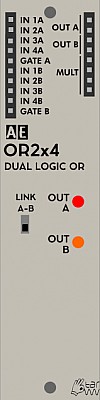
OR 2x4
This module provides an OR logic, where if a signal is at least one of the inputs, it/they will be sent to the output, this is useful for some mixing requirements and combining CVs. The output can also be synced to tempo via the gate in.
Module power consumption: 2 mA
Inputs
There are two separate 4 input OR circuits, A & B. Both have the same inputs/outputs.
- IN 1A - 1 of 4 inputs into the A circuit.
- IN 2A
- IN 3A
- IN 4A
- Gate A - If used, this will control when the output signal is available. If not used the output reflects the inputs directly. Useful for syncing to tempo etc. It can also be used to lower the volume/ voltage of the output.
This is duplicated for the B circuit.
Outputs
- OUT A (2) - Circuit A output.
- OUT B (2) - Circuit B output.
- Mult - A passive mixer/splitter separate to the main module circuits.
Controls
- Link A-B Switch - This makes the module 2 separate 4 input Or circuits, or one 8 input circuit.
Patch Suggestions
If you use all 4 inputs on a circuit, be aware you will have no output if all 4 inputs have a signal. That would be an AND logic out.
This module is excellent for producing non-linear CVs, e.g. combining an LFO and an Envelope module through this can get very interesting.
It works well to combine triggers from the various SEQ16 outputs to get a different pattern to the main sequence.
You may find this link useful. https://doudoroff.com/logic/

ORNAMENT & CRIME
This is a clone of a special and well-known Eurorack module, which offers a hundred ways of processing and generating CV and modulation signals. The AE version behaves in any way just like the Eurorack module (except for the ability of processing negative voltages which simply don't exist in AE) and may well become the brain in your rack. The module is based on a Teensy 3.2 microcontroller board and can easily be reprogrammed. You can choose whether to get the original firmware or the alternative Hemisphere Suite pre-installed.
Module power consumption: 60 mA
Inputs
- CV 1, 2, 3, 4 - Input channels for CV signals. It depends on the currently active mode what these are for.
- TRIG 1, 2, 3, 4 - Input channels for trigger signals. It depends on the currently active mode what these do.
Outputs
- OUT A, B, C, D - CV or trigger outputs depending on the currently active mode.
Controls
These controls are generic and do different things depending on which firmware is installed and which mode is currently active.
- Button Up
- Button Down
- Left Knob
- Right Knob
Original Firmware
The original firmware can be found here: https://github.com/mxmxmx/O_C
The official manual for the original firmware is here: https://ornament-and-cri.me/user-manual-v1_3/#overview
The following modes are available with the original firmware:
- CopierMaschine - is an enhanced version of a quantising four stage analogue shift register (ASR)
- Harrington 1200 - provides basic neo-Riemannian Tonnetz transformations of triadic chords, triggered by the digital (gate/trigger) inputs.
- Automatonnetz - combines Tonnetz transforms with a “vector” sequencer - it can be both a chord sequencer and a melody sequencer, but not of the usual kind.
- Quantermain - is a quad pitch quantiser for external voltages, with editable scales; it can do clocked (trigger-driven) quantising, or continuous quantising, with a latency of under 100 microseconds; it also features quad Turing Machines, May-Verhulst logistic maps or byte beats as optional, semi-random, internally generated CV sources.
- Meta-Q - is a dual-channel quantiser, similar to Quantermain, but also offering scale and note mask sequencing.
- Quadraturia - is a wavetable quadrature LFO, based on the “Easter egg” in the Mutable Instruments Frames module.
- Low-rents - is a dual Lorenz and Rössler (strange attractor) modulation generator, partially based on the “Easter egg” in the Mutable Instruments Streams module.
- Piqued - is a quad voltage-controlled envelope generator, based on envelope generator code from the Mutable Instruments Peaks module, but extending it with voltage control, additional envelope types, including re-triggering (looping) envelopes, additional segment shapes, adjustable trigger delays, and a unique Euclidean “trigger filter” which turns the app into a Euclidean rhythm generator which can output envelopes, not just gate or trigger pulses.
- Sequins - is a dual-channel step sequencer offering 4 “tracks” of up to 16 steps each; tracks can themselves be sequenced.
- Dialectic Ping Pong - is a quad bouncing ball envelope generator, based on a hidden mode of the Mutable Instruments Peaks module.
- Viznutcracker, sweet! - is a quad “byte beat” equation generator, which can be used as an audio source to generate curious but often interesting 8-bit noises and tunes, or which can be clocked by an external source to produce “byte beat” control voltage sequences. “Byte beats” were first described in 2011 by viznut (aka Ville-Matias Heikkilä).
- Acid Curds - is both a chord quantiser (sometimes called a “harmonic quantiser” for external pitch voltages), and a chord progression sequencer.
- References - is a utility app that outputs specific reference voltages on each channel to help tune or calibrate VCOs and other modules. It also includes a high-precision frequency meter and note tuner, a high-precision BPM (beats per minute) tempo meter, and a closed-loop calibration mode.
Alternative Firmware - Hemispheres Suit
This is an alternative firmware which you can install instead of the original. Just follow the instructions in this manual: https://github.com/Chysn/O_C-HemisphereSuite/wiki
Synthdad presents this in detail in this video: https://youtu.be/dg_acylaMZU
The following video is a great overview of the different applets in the Hemisphere Suite: https://youtu.be/mtO5Ua12pgg
Here is the manual for all applets: https://synthmodes.com/modules/o_c_hemisphere/
Patch Suggestions
If you have problems wiht the output CVs being too high, try calibrating the module, as per this thread on the forum:-
https://forum.aemodular.com/thread/2081/cv-output-high-stock-firmware
Synthdad has a whole playlist on YouTube with tutorials and patch suggestions for various original modes and some Hemisphere applets:
https://www.youtube.com/playlist?list=PL-oO_kqREhTeKHHsymeiFvyEeRVmWj0BZ

PHASER
The PHASER module runs the signal through a chain of all pass filters, which brings a very distinctive sound when the filter stages are modulated. Well known is this sound by many pieces of electronic music in the 70's and 80's; especially with the SOLINA as audio source you get this unique spacey sound known from these days. With a switch you can select 4 or 8 stages; more stages make the modulation more deep and intense.
Module power consumption: 4 mA
Inputs
- IN - incoming audio signal
- CV1 - external modulation CV source input
- CV2 - additional external modulation CV source input
Outputs
- Out - output of the phaser sound with dry/wet mix
- WET - only the wet output
- STAGE 1-7 - outputs of the individual phaser stages
Controls
- LFO RATE - speed of the internal triangle LFO
- LFO DEPTH - amount of internal LFO phase shif modulation
- CV 1 - amount of external CV phase shift modulation (CV 1 input)
- SHIFT - manual phase shift control
- FEEDBACK - audio feedback amount
- DRY/WET - mix between the original audio signal and the processed one
- NEG/POS Switch - positive or negative feedback mode produce different sounds
- 8/4 STAGES Switch - choose wether 4 or 8 phaser stages are used. 4 are more subtle, 8 produce a stronger effect.
Demo
Thanks to Felix from The Tuesday Night Machines for this excellent demo video:
Patch Suggestions
If you want to voltage control the dry/wet mix; set the mix to dry and use the main out and the wet out to two separate channels of a VC mixer - e.g. 4VCA or Mixconsole. The main out need not be completely "dry" just set a minimum level with the dry/wet knob, then the CV adds more wet signal.
The Phaser works superbly with the Solina module, but any sounds can be put through it, percussion can be really interesting, as shown to some degree in Felix's video above.
The separate stage outputs can be used to give you separately triggerable sounds via VCAs, again can be really good for percussion. Feeding these outs into different inputs of a mixer, (e.g. Dronx, 4ATTMix) give you more control over the sound, excellent for live use/jams.
The internal LFO is perfect for livening up the sound but CV1 with its accompanying knob to set the level is great for adding other modulation, an envelope is highly recommended, especially on string type sounds, lovely. Can be filter sweep like with varying degrees of subtlety. CV2 can be used as you can set the FX level via the envelope settings.
CV2 has no level control but, of course, this can be done outside this module by the CV going through an attenuator before the input - this could be a VCA with a knob or CV controlling the level. If you just want a knob to control the level the 2ATTCV module can do this perfectly.

POLAMIX
The POLAMIX is similar to the 2CVTOOL in that you can offset, attenuate and invert signals, but it also acts as a 3 channel mixer. Try to use this with 3 LFOs for modulation mayhem!
Module power consumption: 2 mA
Inputs
- IN 1 - accepts any CV or audio signal
- IN 2 - accepts any CV or audio signal
- IN 3 - accepts any CV or audio signal
Outputs
- Bus CV - CV signal from MIDI
- Bus CTRL - CTRL signal from MIDI
- OUT (x2) - output of the 3 channel mix
- MULT - passive multiple, not connected to the module's circuitry
Controls
- OFFSET - Boost or lower the overall level of the output
- LEVEL 1 - Boost or lower the signal level of input 1.
- LEVEL 2 - As above for channel 2.
- LEVEL 3 - As above for channel 3.
Patch Suggestions
This module is excellent for combining CVs, e.g. an Envelope and LFO to go to one destination (e.g. Filter cut off frequency); you can set the level of modulation for each of 3 CVs input, and this is very tweakable during a performance.
It makes an excellent submixer to combine the oscillator outputs for different timbres, this could be the multiple outputs from one VCO or up to 3 separate ones...
Overview video by The Tuesday Night Machines:

POWER
This module is for users who want to save space and don't want or need the midi interface provided by the Master module.
It requires a 9V power supply (min 400ma) to provide the 5V needed for the AE modules. The power is taken to the modules via the Bus cable, which one (or two) you need depends on the case size you have. These items are all available in the Tangible Wave shop.
It also provides a Headphone amplifier (only in mono), and minijack sockets to make connecting the AE to other instruments easier. The Minijack is the same size as on the patch bays of synths like the Behringer Neutron and Arturia Minibrute. These two I/Os will protect the AE from incorrect voltages, for more information please see the 4 I/O module.
Inputs (and outputs)
- I/O 1 - a bidirectional connection from minijack 1 on the front panel to the patch socket labelled 1.
- I/O 2/HP - a bidirectional connection from minijack 2 on the front panel to the patch socket labelled 2
Outputs
- +5 (x2) - Steady +5 volt signal.
- Gnd (x2) - zero volt "signal"
Controls
- HP Vol - controls the loudness of the headphones plugged into minijack 2. The signal provided at the patch bay socket labelled I/O 2.
- AUD/ CV 1 - select the relevant position for whether putting audio or control voltage signals through I/O 1
- AUD/ CV 2 - select the relevant position for whether putting audio or control voltage signals through I/O 2; this needs to be on Aud setting when using headphones.
- HP I/O 2 - When on I/O this behaves the same as I/O 1, when using headphones switch to HP or they will be very quiet!
Display
The red LED lights to show 5V is available, first thing to check if you have no sound....
Patch Suggestions
As mentioned in the introduction, this module is useful to connect the AE to other equipment via the I/O minijack sockets.
If you do ever get a hum from your AE patch wiring, connecting to the GND socket may fix the problem; it will much more often be a faulty patch wire that needs sorting!
With the power supply sold on the Tangible Waves Website, there is enough to power around 4 or 5 rows with either this or the Master module. This module could be used as an expander if a 2nd Midi in was not needed.

QUANTIZER
The QUANTIZER takes four different CV inputs and processes them in a way that the CV values "snap" to the exact values so that oscillators controlled by the outputs of the module play the notes of a selected musical scale. With an encoder one of 16 scales can be selected and is displayed in a text display,
There are 4 independent channels that are quantized to the same selected scale.
Module power consumption: 15 mA
Inputs
- CV 1 - accept CV for channel 1 of the quantizer
- CV 2 - accept CV for channel 2 of the quantizer
- CV 3 - accept CV for channel 3 of the quantizer
- CV 4 - accept CV for channel 4 of the quantizer
Outputs
- CV 1 - Quantized CV from channel 1 of the quantizer
- CV 2 - Quantized CV from channel 2 of the quantizer
- CV 3 - Quantized CV from channel 3 of the quantizer
- CV 4 - Quantized CV from channel 4 of the quantizer
- TRIG 1 - Gate signal on change of CV from channel 1 of the quantizer
- TRIG 2 - Gate signal on change of CV from channel 2 of the quantizer
- TRIG 3 - Gate signal on change of CV from channel 3 of the quantizer
- TRIG 4 - Gate signal on change of CV from channel 4 of the quantizer
- MULT - unbuffered multiple, unconnected from the module's circuitry
- B. CV - CV signal from MIDI (via Master module)
Please note:
The notation of the outputs is slightly different on the panel than indicated here. There are two rows of identical outputs, side by side. For each output-trigger there is an activity LED, indicating a change in quantized CV.
Controls
- SCALE Knob - selects the current scale. 16 scales are available, the selected scale will be displayed in the small display to the right of this knob
- LOCK Switch - prevents accidental changes of the selected scale when activated
- OFFSET Knob - Select from up to 12 notes from the well-tempered scale as base-value, depending on the scale selected. All left would be equivalent to a key of C
Please note:
Scale selection directly takes place when the SCALE Knob is turned, clicking it has no specific effect.
Available SCALES, as indicated on the display, are as follows:
- Minor (e.g. equivalent to A-B-C-D-E-F-G in ‘A minor’)
- Major (e.g. equivalent to C-D-E-F-G-A-B in ‘C major’)
- Dorian (e.g. equivalent to C-D-Eb-F-G-A-Bb in ‘C Dorian mode’)
- Phrygian (e.g. equivalent to C-Db-Eb-F-G-Ab-Bb in ‘C Phrygian mode’)
- Lydian (e.g. equivalent to C-D-E-F#-G-A-B in ‘C Lydian mode’ )
- Mixolyd [Mixolydian] (e.g. equivalent to C-D-E-F-G-A-Bb in ‘C Mixolydian mode’ )
- Locrian (e.g. equivalent to C-Db-Eb-F-Gb-Ab-Bb in ‘C Locrian mode’)
- Gypsy (e.g. equivalent to C-D-Eb-F#-G-Ab-B in ‘C Hungarian minor scale’ )
- Whole (equivalent to C-D-E-F#-G#-A# or B-Db-Eb-F-G-A as ‘Whole tone scales’)
- Pent Min [Pentatonic Minor] (e.g. equivalent to C-Eb-F-G-Bb in ‘C Minor pentatonic’)
- Pent Maj [Pentatonic Major] (e.g. equivalent to C-D-E-G-A in ‘C Major pentatonic’)
- 1-3-5 (e.g. equivalent to C-E-G in ‘C’)
- 1-3-4 (e.g. equivalent to C-E-F in ‘C’)
- Fifth (e.g. equivalent to C-G in ‘C’)
- Octave (e.g. equivalent to C in ‘C’)
- Chromat (The 12 welltempered notes of the chromatic scale)
Patch Suggestions
The most obvious use is to transform any CVs to fit the scale you are using, to then control the pitch of VCOs and the Solina module. It can also be interesting on LFOs and filters.
here is the Quantizer used on a sequencer CV...
It can also be used for other things, e.g.
Using the QUANTIZER as a rhythm generator:
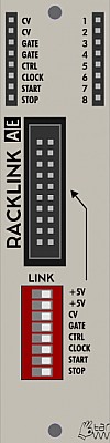
RACKLINK
This is actually 2 modules with a connecting cable. This is for joining 2 of the original AE Modular racks together - these modules are not needed for the current racks. The Racklink is also used by many users making their own cases.
Inputs
The sockets on the left (usually input) side of the AE Module are actually outputs created from Midi via the Master module and AE Modular bus.
- CV - midi note selection changes value
- CV - ditto
- Gate - +5V signal when key/pad is pressed/held
- Gate - ditto
- Ctrl - CV created by controller assigned to Midi CC20
- Clock - midi clock (24 pulses per quarter note)
- Start - Pulse of +5V when Midi start is pressed.
- Stop - Pulse of +5V when Midi stop is pressed
Outputs
The sockets labelled 1-8 on the right (usually output) side of the AE module are bi-directional. The idea is you can patch from one rack to the other without having your patch cable having to go across the gap; this can be very helpful as it is quite easy to knock the longer patch wires out.
Controls
The DIP switch panel lets you select which signals will go to the 2nd rack. Not sure why you would want to stop one, but nice facility to have for trouble shooting etc.
Patch Suggestions
The Racklink is useful to give you more bus CV/clock outs but owners of newer AE Modular cases should not need these modules.
The sockets labelled 1 to 8 mean you do not have to have patch wires trailing across from one case to the other; this can be really helpful to reduce clutter, and creates less need for longer cables.
Rains
RAINS is the AE modular adaption of Mutable Instruments' Rings module. Rings was (as not in production anymore) a resonator.
When something resonates, by being hit, plucked etc. the material has frequencies that are naturally created; this is why acoustic instruments like guitars, drums, cymbals etc. have distinctive sounds; this can be subtle to wildly differing sounds for the same hit/note played. A resonator recreates this natural behavior enabling more "realistic" emulations of acoustic sounds or, much more fun, making a synthesised sound seem more natural to our ears. It can also create a whole other areas of sound for the synthesist to explore....
There are also some hidden modes; see the patch suggestion section for more information.
Module power consumption:
Inputs
- IN - For an audio source you want to affect with the rains; this is optional for the Rains module to make noise. Can also be a trigger in.
- V/OCT - Use this to change the frequency/pitch(es) of the resonator.
- STRUM - For polyphonic use mainly, but always works as a trigger in.
- STRUCT CV - For use in conjunction with the Structure Knob below.
- FREQ CV - Use this to change the frequency/pitch(es) of the resonator, but not the main signal.
- Brightness CV - For use in conjunction with the Brightness Knob below.
- Damping CV - For use in conjunction with the Damping Knob below.
- Position CV - For use in conjunction with the Position Knob below.
Outputs
- Out (x2) - Main signal and all harmonics etc mixed together.
- Odd Out - In Mono mode (see below), Odd numbered harmonics only - useful for adding "grit"/dirtiness to the sound quite often. In Poly mode, does the 1st, or 1st & 3rd voices only.
- Even Out - In Mono mode (see below), Even numbered harmonics only - useful for thickening the sound quite often. In Poly mode, does the 2nd, or 2nd & 4th voices only.
These "individual outs" are useful for changing the sound further just by mixing back in with the main out, or processing with FX etc.
- Mult - a non-buffered mixer/divider circuit seperate to the module electronics.
Controls
- Poly Button - this sets whether the Rains is in mono, duo or polyphonic mode. The latter is 4 voices. What this essentially means is that the sound gets more complex as you add more voices.
Green LED - one voice, Yellow 2 voices and Red 4 voice.
-
Type Button - this sets the way the Rains module behaves.
-
Green LED - Modal resonator - simplest, similar to a string/tube being plucked/hit
-
Yellow LED - Sympathetic strings - more complex adding tones to the orginal signal as well as similar behavior to the modal resonator.
-
Red LED - Modulated/Inharmonic strings - the most complex adding further to the s.s. mode by using time delay modulation and different filtering. Can get Bell like tones in this mode.
The 4 CV +/- knobs control the effect of the CV at the appropiate input for the parameter labelled by the knob to the CV knob's right. E.g. The Damping CV input is controlled by the 3rd knob down in the left column.
This control can be an increase to the knob position (+ side of the dial) or deducted form the knob position (- side of the dial). If the knob is centred, (vertical), the CV has no impact on the sound.
-
Structure - This control emulates the material something is made of, so sets the resonant frequencies generated.
-
Brightness - This controls the amount of higher frequencies in the sound.
-
Damping - This controls how long the resoanant sounds are produced for, at longer times it can start producing more harmonics from its own sound in some circumstances.
-
Position - This emulates where, if this was a physical object, it was hit. All drummers know the sound is affected by where you hit the pad for instance. It is somewhat like a comb filter in action, (though less boring than that sounds!) and changes the harmonics in the signal more subtely as a rule (which can be broken).
Patch Suggestions
This is not a normal filter module! I highly recomend starting off quite simple; use 2 LFOs and put one in IN or STRUM and move the other around to see what each parameter does.
The Rains module can make some very lush/full string sounds and similar, so the Phaser, Multifx and Spring Reverb are great with it.
It begs to have lots of CVs put into it, so envelopes, LFOs etc are needed. Of particular note are Modulators, the Joystick module and Sloth.
To combine the 3 different outs the Polamix is ideal.
It can do some excellent tuned percussion sounds with no inputs, triggered from a sequencer like the TRI164 means the other channels could trigger other sounds in time with it, or envelopes to affect the Rain's sound....
The Rains has the most impact on incoming noises if they are fairly simple but, having said that, it can make some incredible sounds when fed from the Wavetables Oscillator.
It is well worth experimenting with the different modes of Poly & Type, One I found particularly nice when just triggering the Rains on its own was Green LED on Poly and Orange LED on Type.
There are also several hidden "easter egg" modes, as per the original module; this link explains them pretty well, LINK, but this video by faux cyrillic is specific to the Rains and really helpful:-
Mini:
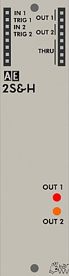
SAMPLE & HOLD
A module whose output voltage is set by "sampling" the input voltage when triggered. This is usually for producing random notes/modulation in conjunction with the NOISE module.
There are 2 independent Sample & Hold circuits within this module.
Module power consumption: 2 mA
Inputs
- In 1 - The source for where the voltage will be selected from.
- Trig 1 - For a pulse to tell the module to take the voltage reading of input 1 and send that value to output 1.
- In 2 - The source for where voltage will be selected from.
- Trig 2 - For a pulse to tell the module to take a reading from input 2 and send that value to output 2.
Outputs
- Out 1 (2) - The voltage selected by In/Trig 1 is available here.
- Out 2 (2) - The voltage selected by In/Trig 2 is available here.
- Thru (4) - On older modules marked Mult as a passive mixing/signal splitter as per many other AE Modules.
Controls
This module has no performance controls.
Patch Suggestions
This video describes how to use the SAMPLE&HOLD module and makes use of the 2ATTCV module for generating CVs:-
This is quite an old video so it doesn't suggest using the QUANTIZER module to make the pitch CVs match a key; with this, a sample & hold circuit can produce sequencer type CVs. Triggers can be from many modules including TRIQ164, TOPOGRAF or BEATDIVIDER
Try using an LFO instead of noise as the input source, quite handy for modulation but can be good to give a restricted random arpeggiator type sequence if used on the pitch of the VCO(s).
Using Noise, the Voltage variation is about the maximum the AE Modular can deal with, so use of some form of attenuation is usually needed - the 4ATTMIX, 2ATTCV or Mixer 4-4 modules can do this.
With attenuation, this module can be really good to give a bit of variation to a sequence by varying the filter on the sound - use the 2ATTCV module to combine the envelope and S&H outputs to the Filter module. It's also good on resonance on the Nyle filter. Use the same trigger as the sequence if you want to be in sync with that, and can change timing(s) with use of one of the logic or divider modules.
It can produce bit crusher style results when used to sample audio signals.

SAMPLYR
This module plays back audio files from an SD card.
Module power consumption: 25 mA
Inputs
- CV - Control Voltage for the pitch
- GATE - Gate control for the length of the sample playback when in loop mode, trigger when in one-shot mode. In loop mode the sample will only play while the gate is high.
- START - Voltage determining at which position the sample will start playing. 0V will play at the start and ~5V will be the end of the sample. If the sample is very long (SAMPLYR can play samples which are hours long) the accuracy of this will degrade.
- LP STRT - Voltage determining where the loop will start, independently from any per sample settings.
- LP LEN - Voltage determining the length of the loop, independently from any per sample settings.
- REVRSE - Gate control for playing the sample backwards. As long as the gate is high the sample will play in reverse.
- LP ON - Gate control for playing the looping part of the sample, independently from any per sample settings. As long as the Gate is high the loop will play.
- SMP SEL - Voltage to select a sample from the current folder, eg. if the currently playing sample is in folder D then this voltage will select any of the 10 samples in folder D.
Outputs (on the left)
- B. CV - MIDI pitch as transported through the bus.
- B. GATE - MIDI gate as transported through the bus.
Outputs (on the right)
- OUT - The audio of the sample playback
- LP STRT - A trigger signal when the loop starts (Please note: this mainly is intended to detect the very first loop-start, for continuous looping it will typically trigger at the same time as LP END)
- LP END - A trigger signal when the loop ends (this repeats for as long as the loop repeats)
- SMP END - A trigger when the sample playback ends
Controls
- FREQ Knob - Changes the pitch of the sample playback in addition to the CV control. Pitching of a sample is achieved by changing the sample playback speed, so the higher the pitch, the shorter the playback and vice versa for lower pitch.
- SELECT/EDIT Knob/Button - Multi function select knob and push button. When in playback mode, turning the knob will select the next/previous sample. Pushing the button opens a menu on the display (more info below).
- 0 / START - When in playback mode this button will select any sample which was assigned to this bank of presets (Within a range of names from '0' to '5'). In edit mode this is a shortcut to change the sample playback starting position.
- 1 / LP STRT - In playback as above. In edit mode shortcut to loop starting position.
- 2 / XFADE - As above. In edit mode shortcut to the cross fade menu
- 3 / END - As above. In edit mode shortcut to change the sample playback end position.
- 4 / LP LEN - As above. In edit mode shortcut to change the loop length
- 5 / LP MODE - As above. In edit mode shortcut to change the looping mode (loop or one-shot)
Display
The display shows the folder and file number of the currently selected sample at the top. Below it shows the waveform of the sample (amplitude over time) rotated 270 degrees into vertical and the following markers:
- Sample start - this is marked as the beginning of the filled waveform
- Loop start - this is marked as a horizontal line to the left of the loop range
- Loop end - this is marked by a horizontal line at the end of a dotted vertical line which marks the extent of the loop
- Depending on the loop mode, a triangle at the beginning/end of the loop range indicates the playback direction.
- Sample End - this is the bottom of the fille waveform
When in Edit mode, the display can also display information about the currently selected sample, such as filename, size, length and other info. It will also show the parameter which is currently editable, eg.
- sample start
- sample end
- loop start
- loop end
- cross fade (xfade)
- loop mode
Edit Mode
To enter the edit mode, click the encoder; then, the program number is replaced with the menu options. Turning the encoder scrolls through the menu options; a further click selects the editing of the according value, like start/endpoints, loop points etc. Turning the encoder changes the value, another click on the encoder returns to menu selection. The leftmost menu option is "Save"; clicking here stores the defined settings. The menu item WAVEFRM rebuilds the waveform graphics; this is useful when the actual WAV file on the card has been replaced. (The graphics is only generated once and stored then.) The menu item WAV INFO shows the full filename and other file related info.
Global settings
In the menu, the rightmost menu items are stored globally:
- CV tracking calibration
- Hot change mode - When ON then on a sample change the playback will start roughly where the other sample was when the change was initiated, or if this doesn't work at the loop start. This makes the module behave like a radio when scanning through the stations.
Micro SD Slot
You can insert any Micro SD card which is formatted with FAT32.
In principle the following cards could be supported:
- SD: Up to 2 GB
- SDHC: over 2 GB to 32 GB
- SDXC: over 32 GB to 2 TB
FAT32 only supports a maximum partition size of up to 2TB and individual file size of up to 4GB.
This gives us the following maximum length of an individual sample (WAV 8bit uncompressed, mu-law or alpha-law):
- 4GB/32khz: 34 Hours : 43 Minutes : 20 Seconds
- 4GB/16khz: 69 Hours : 26 Minutes : 40 Seconds
HOWEVER: When loading a sample for the first time its waveform is calculating for the display and then stored along with the sample. As this is a very tiny processor it can take a long time for very long samples ... maybe even hours!
SD Card file fragmentation - SAMPLYR plays samples directly from the SD card and expects all files in byte order. If you encounter issues with playback this could be the result of a fragmented file system. It would be best if you copied all files from the SD card to your computer and then format the SD card (not quick formatting) and then transfer the files back onto the card. This will ensure that the files are stored in order and can be read from the SAMPLYR software.
How to organize Samples on the SD Card
To keep things simple, the files on the SD card are organized in a fixed structure:
- The card can contain in its root a number of folders, named with exactly one letter, from "A" to "Z"
- The files are named beginning with a number from "0" to "9"; the full filename can be longer and be descriptive, but the SAMPLYR only checks for the first letter. Only 10 files per folder are allowed.
- The extension is always ".WAV".
How to prepare Samples
The samples must be WAV files, with a resolution of 8 bits and mono. The encoding can be either PCM (simple, straight 8bit audio), or being encoded as uLaw or aLaw. These are encodings that allow a little higher bit depth, in case of the SAMPLYR this is 10 bits effectively.
The preparing/converting of samples for he SAMPLYR can be done e.g. with the open-source audio editor software Audacity (see https://www.audacityteam.org/ ).
The basic steps for converting an existing sample for SAMPLYR are the following:
- Open the audio file in Audacity
- In case it's a stereo sample: Click menu Tracks > Mix > Mix Stereo Down to mono...
- Amplify the sample to use the full volume resolution (bit-depth): Click Effect > Volume and Compression > Amplify... , then New Peak Amplitude (db) to "0" (Make sure to select the complete sample for this operation, typically by clicking on it and applying CTRL-a / CMD-a)
- First of all make sure to set the "Project Rate (Hz)" at the left bottom corner to your preferred Samplerate, up to 32000
- Set the sample rate for export: Go to menu Edit > Preferences, Audio settings, (or Tracks > Samplerate in some versions of Audacity) set "Default Sample Rate" to the identical rate as the Project Rate.
- Click File > Export > Export as WAV... and set encoding to Unsigned 8-bit PCM, or U-Law or A-Law
- ... DONE!
Samplerates of 16000, 22050 or 32000 are recommended (and are usually stored for future sessions). Please note: when 32khz is used you get the best results, but you then can pitch the sample only about one note upwards, so in that case please make sure your material is optimized to be played with lower notes/CVs from 0 to (slightly above) 4V (given that the source-material is tuned/should be set to C). As explained above, the relative adjustment in terms of which note/CV will result in what playback speed/frequency for this can be done with the FREQ Knob.
Especially when using samples with low volumes / higher dynamic-ranges the usage of U-Law (or A-Law) is recommended, U-Law typically also was used with vintage samplers from the early 80th. U-Law has a higher dynamic range (14 bit), but more distortion with low volumes than A-Law (12 bit). Because of the 10bit DAC of SAMPLYR, thus you may find A-Law preferrable. Experimentation may be needed to find the best possible results! Also compression/limiting of the material prior to exporting for a specific format can increase the quality. Of course, you can apply all the processing methods Audacity offers (which is quite a lot!); check the documentation for this. In any case, it's recommended to do all processing on a file with the highest resolution and sample rate, and reduce it to the 8-bit WAV only as the last step.
Patch Suggestions
This video shows some demo sounds and rough overview of the module's features:

SAWVOX
The SAWVOX module is a “complete” synth voice with two sawtooth oscillators, a filter and a VCA, all realized digitally with a tiny 8-bit microcontroller. The oscillators are detuned by a fixed rate to get a fatter sound, and can be switched to a single oscillator. Of course, due to the limited resources of the processor, the sound has the typical 8-bit lofi char, but the CV tracking is quite fine, and it can find its place in a lot of patches. All parameters can be CV controlled, eg. filter frequency and resonance.
The module is based on a simple 8-bit microcontroller and an adapted design of Jan Ostman.
Module power consumption: 30 mA
Inputs
- CV1 - CV frequency control
- CV2 - additional frequency control which is added to CV1
- FLT CV - filter cutoff frequency control
- RES CV - filter resonance control
- AMP CV - VCA amplitude control
Outputs
- OUT - audio output signal
- MULT - multiple disconnected from module circuitry
- B.CV - CV signal from MIDI bus
- B.CTRL - MIDI CTRL signal from the bus
Controls
- PITCH (pot) - select the base frequency of the oscillator
- FILTER (pot) - select the cutoff frequency of the built-in filter
- RESONANCE (pot) - select the resonance of the filter
- OSCILLATORS (switch) - select 1 or 2 oscillators. If 2 is selected the second oscillator is detuned to the first one at a fixed rate.
- +2 OCT (switch) - if set to the top position the frequency is shifted up 2 octaves
Patch Suggestions
Though technically a "complete" voice it obviously can be processed further within the AE system. PHASER and Lofi Delay are particularly recommended....
If you haven't got the fine control you desire for a particular patch then, as an example, if you leave the Sawvox filter fully open you can patch the output to another AE filter to have more parameters/adjustments available.
Here is a video by The 5th Volt which features this module.
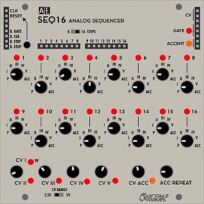
SEQ16
There is a user guide for this module on the Tangible Waves shop SEQ16 page which contains some of the information as found here. This is a complex module; if an explanation here isn't working for you, it is worth giving it a try.
A 16 step sequence suits many styles of music, and is needed for "Berlin School " EM. If you only need 8 steps usually, you can consider the SEQ16's little brother, the SEQ8. There are slight differences too, in general the SEQ16 has more possibilities. There could be reasons to have both in a larger AE system!
You can download a printable manual for offline reading: seq16_manual.pdf
Module power consumption: 7 mA
Inputs
- CLK - Clock, each +5V pulse moves the sequence to the next step.
- RESET - Puts the sequence being played back to step 1; this means any sequence length up to 16 steps can be generated.
The other sockets on the "input" side of the module are actually outputs so will be listed below.
Outputs
On the left side of the module:
- B. GATE - This is +5V as long as a key is pressed on a midi keyboard connected via the Master module.
- B. CLK - This is the midi clock via a device connected via the Master module; as this is 24 pulses per quarter note, this will need dividing down to the required tempo using one of the divider modules in the AE system.
- B. STRT - A single pulse generated when the start key is pressed on a midi device connected via the Master module.
- B. STOP - A single pulse generated when the stop key is pressed on a midi device connected via the Master module.
In the middle of the module:
- 1-16 - these are individual outs for each step of the sequence, it is however just a +5V trigger, not a CV. Still useful, the main job it is for is to set the sequence length with the reset input.
On the right side of the module:
- OUT (x3) - the CV generated by the sequence
- GATE (x3) - this generates a +5V signal for each step, unless the step is set to P (pause) or ACC (accent, more below)
- ACCENT (x2) - this generates a +5V signal for each step where it is set to ACC (accent, more below)
Controls
- Knobs 1-16 - One for each step of the sequence; it can be set to positions 1 to 5 (in Roman numerals), which correspond with the relevant CV knob at the bottom of the module. In these positions a gate signal is also sent to the gate outputs. There is also P (pause, no trigger is sent to the gate output although the CV of the previous step will still be provided on the CV out), and ACC (accent) which will be covered under that control knob.
- CV 2 to 5 - CV 1 is 0 volts, so the CV will leave the pitch of your VCO (for instance) alone. CVs 2 to 5 are set by the relevant knob on the module.
- CV ACC - This sets the main output CV when ACC is selected on a step knob, a simple use is just to be another pitch in a sequence but more can be done as you will see in patch suggestions below. Using ACC also generates a a signal on the ACC outputs as mentioned above.
- ACC REPEAT - When ACC is selected on a step knob, the gate output can be set to between 1 and 8 +5V triggers per sequence step. This knobs sets the amount.
- 8 16 Steps switch - you could do this with a patch wire from step 8 individual out to the reset input, but this is a more elegant solution. 8 and 16 steps are the 2 most common sequence lengths for most modern western music as they fit 4/4 time easily.
- CV Range switch - This controls whether the SEQ16 goes from 0 to 2.5V or 0 to 5 volts at the CV out. This can be useful for controlling pitch when going to VCOs, or if being used a a modulation source.
LED Indicators
-
1 - 16 - one for each step of the sequence, lit when that step is "playing"
-
GATE - lit when there is a gate signal present at the output.
-
ACCENT - lit when there is a signal present at the output.
-
CV1 to CV5 - lit when that CV has been selected by the current step in the sequence.
-
CV ACC - lit when that CV has been selected by the current step in the sequence.
Patch Suggestions
Unless you have a non-Midi system, you will need either the Beat divider or MM Divider module to step down the very fast MIDI clock to a usable clock; the former is simpler but the latter gives you many more options....
https://wiki.aemodular.com/pmwiki.php/AeManual/BEATDIVIDER
https://wiki.aemodular.com/pmwiki.php/AeManual/MM-DIV
The main intention of this module is to provide pitch CV to oscillators, with the gate outputs for VCAs, envelope generators etc.
It can be really good as a modulation generator on e.g. filter cut off. This can use the same CV as the VCOs so the filter opens more as the pitch is higher. The CV can, of course, be processed by any of the various modules like slew/edge, 2CVTool etc. With 3 CV outs, the SEQ16 is ripe for this...
The ACC out can be used to trigger additional sound (e.g. a VCA controlling a noise source), additional pitch variation in your sequence (via an attenuator like the 2ATTCV module), filter cut off frequency (best via an attenuator again) many other things that can vary your sequence/sound very nicely!
The individual trigger outs can also be used to vary your sequence, by using an attenuator again to give you control over the amount (pitch) just connect to an input of the relevant VCO. If your input(s) are full, use a 4ATTMIX or similar to combine the CVs before going to the VCO. The 2ATT/CV and 4ATT/MIX give you the attenuation/ control required.
If you are using an LFO to clock the SEQ16, it can be really interesting to feed a CV back to the LFO rate, again an attenuator will give you fine control.
For the more experimental among you, using a LOGIC module, or other trigger manipulation into the reset input can be interesting. Doing the same in to the clock input can be excellent as long as it all stays in time with the rest of the music!
Here is a tutorial video made by The 5th Volt: https://youtu.be/xK-1NDD-RyQ

SEQ8
The SEQ8 is an 8-step sequencer for controlling oscillator pitch and triggering envelopes etc.
An 8 step sequence is great for dance music, basslines in particular. This is a reason to pick the SEQ8 over its bigger brother the SEQ16, that and needing less rack room. There are other slight differences too, in general the SEQ16 has more possibilities. There could be reasons to have both in a larger AE system!
Compared to "classic" analog sequencers the SEQ8 works a bit differently: Instead of setting the CV for each step independently (which means in fact "tuning" each step which can be a bit tedious), it has 4 knobs for presetting different CV's (= notes); each of the 8 step knobs selects one of these CVs, plus 0V (=base note) plus Pause (no trigger output). So some CVs have to be fine-tuned once; with the step knobs you can focus entirely on the sequence itself and you can even modify it on the fly, still remaining in tune.
Additionally to the selected CV presets, the "raw" value of the step knobs is also output.
Module power consumption: 7 mA
Inputs
- CLK - Clock, each +5V pulse moves the sequence to the next step.
- RESET - Puts the sequence being played back to step 1; this means any sequence length up to 8 steps can be generated.
- MODE CV -
The other sockets on the "input" side of the module are actually outputs so will be listed below.
Outputs
On the left side of the module:
- B. GATE - This is +5V as long as a key is pressed on a midi keyboard connected via the Master module.
- B. CLK - This is the midi clock via a device connected via the Master module; as this is 24 pulses per quarter note, this will need dividing down to the required tempo using one of the divider modules in the AE system.
- B. STRT - A single pulse generated when the start key is pressed on a midi device connected via the Master module.
- B. STOP - A single pulse generated when the stop key is pressed on a midi device connected via the Master module.
In the middle of the module:
- 1-8 - these are individual outs for each step of the sequence, it is however just a +5V trigger, not a CV. Still useful, the main job it is for is to set the sequence length with the reset input.
On the right side of the module:
- OUT (x3) - the CV generated by the sequence
- GATE (x3) - this generates a +5V signal for each step, unless the step is set to P (pause) or ACC (accent, more below)
- CV RAW (x2) - this is the CV generated by the actual step knob, so it changes with each step but not to the CV set by the relevant CV knob. useful for modulation effects.
Controls
- Knobs 1-8 - One for each step of the sequence; it can be set to positions 1 to 5 (in Roman numerals), which correspond with the relevant CV knob at the bottom of the module. In these positions a gate signal is also sent to the gate outputs. There is also P (pause, no trigger is sent to the gate output although the CV of the previous step will still be provided on the CV out)
- CV 2 to 5 - CV 1 is 0 volts, so the CV will leave the pitch of your VCO (for instance) alone. CVs 2 to 5 are set by the relevant knob on the module.
LED Indicators
-
1 - 8 - one for each step of the sequence, lit when that step is "playing"
-
CV1 to CV5 - lit when that CV has been selected by the current step in the sequence.
Patch Suggestions
Unless you have a non-Midi system, you will need either the Beat divider or MM Divider module to step down the very fast MIDI clock to a usable clock; the former is simpler but the latter gives you many more options....
https://wiki.aemodular.com/pmwiki.php/AeManual/BEATDIVIDER
https://wiki.aemodular.com/pmwiki.php/AeManual/MM-DIV
The main intention of this module is to provide pitch CV to oscillators, with the gate outputs for VCAs, envelope generators etc.
The individual trigger outs can also be used to vary your sequence, by using an attenuator again to give you control over the amount (pitch/filter amount etc.). If your input(s) are full, use a 4ATTMIX or similar to combine the CVs before going to the destination. The 2ATTCV and 4ATT/MIX give you the attenuation/ control required.
Taking the previous further, using one of the various outputs, individual trigger out to an envelope is good, you can affect the sound, e.g. filter cut off, vibrato, volume etc. This is a a large rabbit hole...
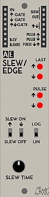
SLEW / EDGE
The SLEW/EDGE module combines the function of a slew limiter for CVs and a CV change detector in one module. Slew is a method of slowing the rate of change of a CV signal, i.e. the changes are less abrupt thus being useful for things like portamento. The slew operation can be activated individually for rising and/or falling CVs.
The other function is edge detection, which can generate various gate / trigger output signals depending on the rise and fall of the input CV; this information is available on different outputs.
Module power consumption: 5 mA
Inputs
- IN - accepts the CV or audio signal which will be shaped
- ↑ GATE - gate signal (+5V) that activates slew on rising input CV, if the slew ↑ switch is off.
- ↓ GATE - gate signal (+5V) that activates slew on falling input CV, if the slew ↓ switch is off.
- ⇅ GATE - gate signal (+5V) that activates slew for all input CV changes, this is useful if you have one of the switches below set to slew on, and want the other to be active sometimes as well.
- B.CV - MIDI CV signal from bus (from Midi keyboard via Master module)
- B.GATE - MIDI Gate signal from bus (from Midi keyboard via Master module)
Outputs
- SLEW OUT - The slew processed input signal
- ⇅ - this output is high (+5V) if the last input change was a rising voltage and low (0V) if the input was falling
- PULSE ↑ - this sends a short pulse each time the input voltage is rising
- PULSE ↓ - this sends a short pulse each time the input voltage is falling
- PULSE ⇅ - this sends a short pulse each time the input voltage is rising or falling
LED Indicators
- LAST ↑ - this LED lights up if the last input voltage change was rising
- LAST ↓ - this LED lights up if the last input voltage change was falling
- PULSE ↑, PULSE ↓ - this LED reflects the PULSE ↑ / PULSE ↓ outputs
Controls
- SLEW ON ↑ - activates slew on rising input voltages, if this switch is on the gate input has no effect.
- SLEW ON ↓ - activates slew on falling input voltages, if this switch is no the gate input has no effect.
- LOG/LIN - changes the characteristic of the voltage change between linear and logarithmic, the latter gives bigger changes as a rule.
- SLEW TIME - this knob sets the rate the CV will change, from almost instant to some changes will not have time to show at the output!
Patch Suggestions
If the CV is used e.g. for controlling an oscillator, you can get portamento between pitch CV changes. With the two switches (or the Gate ins), it can be controlled to be only on rising or falling CVs or both. Just patch the cable that was going to the oscillator to this module's input, and the Slew Out to the Oscillator.
The Slew detector can be useful if using the S&H module for modulation; rather than jumps it will smooth the changes between the different levels, particularly good on filter modulation, unless you want sudden changes.
This module can be good on a LFO to , in effect, vary the wave shape - try with a square wave first and you will understand more quickly.
This module can be a way of making an LFO more of a master clock, with the various edge outputs triggering at different times in the waveform cycle. ⇅, PULSE ↑, PULSE ↓ & PULSE ⇅ - experiment, very good for a percussion track but one(or more) outputs could be the clock on the sequencer module....

SOLINA
The SOLINA String Machine is a digital string synthesizer module for lush pad sounds, based on Jan Ostman's DSP code. It features extensive chord generation options and offers various adjustable sound shaping parameters, like oscillator detuning and vibrato.
Module power consumption: 11 mA
Inputs
- CV - CV input for chord selection
- CH. VAR CV - CV input to select the chord variants (inversions, raised thirds, etc.)
- CHORD + - Trigger input to play the next chord in the progression preset
- CHORD - - Trigger input to play the previous chord in the progression preset
- 4th GATE - Gate input. switching the 4th note on (high) or off (low)
Outputs
- BUS CV - (positioned on the left side) Pitch signal from the MIDI bus
- BUS GATE - (positioned on the left side) Gate signal from the MIDI bus
- OUT - Audio output
- MULT - Unbuffered multiple
Controls
Chord generation and playback:
- COARSE FREQ knob - tunes the root note of the chord (quantized to semi tones)
- FINE FREQ knob - tunes the root note of the chord (unquantized)
- +1 OCT switch - transposes the chords up by one octave
- CHORD knob - selects the chord to be played
- CHORD + / - buttons - step through a preset chord progression (1-4-5, etc.), if the CHORD knob is set all the way counterclockwise
- CHORD VAR knob - selects different chord variants. Middle position is the standard position for regular chords. In the left half there are inversions and in the right half there are variants with raised or lowered 3rds or 5ths, as well as 5ths-only at the full clockwise position.
- MAJ/MIN SCALE switch - switches between major or minor scale
- 4TH NOTE ON switch - adds a fourth note to the chord
- 7th / BASS switch - selects the 7th or the Bass note as 4th note
Sound shaping:
- OSC SPREAD knob - slightly detunes the individual notes for a wider, moving sound
- TONE knob - blends between a lo-fi digital low pass and high pass filter effect
- LFO RATE knob - adjusts the vibrato speed
- PITCH MOD knob - adjusts the vibrato amount
- ENSEMBLE MIX knob - blends in a phaser effect
Patch Suggestions
For authentic 70s strings, (or just great sound sin general), the PHASER module is a great partner for the Solina.
Chord generation and playback is actually quite easily done, even though it can seem very complex, especially if you're not well versed in music theory. Start with all knobs turned fully counter clockwise, except for the CHORD VAR knob, which should be at its middle position. Then tweak the COARSE and FINE FREQ knobs to tune the root note chord to your liking or to other sounds in your patch. After that, choose MAJOR or MINOR as a scale and turn the CHORD knob to hear which of the available chords fit your music piece. You may sequence them then via the CV input. For more interesting chords, set the CHOR VAR knob to a different position and listen to the chords again (not all will necessarily change). Also switch on a 4th note if you like.
Usage of the CHORD + / - buttons and trigger inputs to step through common chord progression presets (1-4-5, etc.) requires the CHORD knob to be fully counterclockwise and no voltage present at the CV input. The chord progressions let you instantly play pleasing chords to your tuned root note and set scale. This is practical if you just want to create a quick backing chord track to your patch. In case you want to sequence the chord changes with triggers from a sequencer, it is helpful to do so via a 3VCSWITCH module together with a DIVIDER or MM-DIV module. This combination will allow you to route your sequencer triggers to either the CHORD + or CHORD - input, to play up and down a chord progression. The chords in the progression presets do not wrap around, so there will be a point when + or - won't step any further and you have to use the opposite button/trigger input to play the progression backwards again.
As with any modular synth oscillator, go ahead and route the SOLINA's audio through other modules, like filters, VCAs, a WAVEFOLDER and MULTIFX to further shape its sound and apply rhythm to the strings.
Don't Forget the PHASER module....
An excellent video guide to the Solina by The Tuesday Night Machines: https://youtu.be/R3lDrnbjHHQ
Superbooth 2019 prototype sound demo video by The Tuesday Night Machines: https://youtu.be/OGV4r7Wq6B8
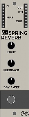
SPRINGREVERB
Spring reverbs were an early attempt to create electronic reverb audio effects without requiring an actual large space or echo chamber. While their sound might not be very natural, its unique characteristics have gathered a big following among musicians. Spring reverbs are also relatively small and affordable.
The SPRINGREVERB module is an interface for typical external spring reverb tanks, which are also used in guitar amplifiers:
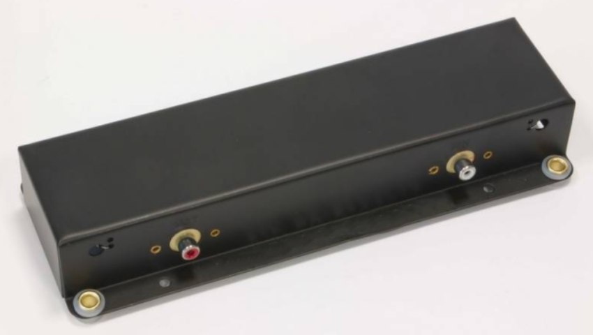
A tank is obligatory and a mid-sized version, like the one pictured above, can be purchased together with the module from the tangible waves online store. It connects to the module via a 3.5mm TRS to stereo RCA cable.
Other reverb tanks and sizes are available at various places online and offer different sound characteristics, for example longer or shorter reverb times.
Module power consumption: 5 mA, 14 mA as complete set with spring-tank SPRINGREVERB (complete set)
Inputs
- IN - audio signal input
Outputs
- OUT - dry/wet mix audio signal output
- WET - wet-only audio signal output
Controls
- INPUT - audio signal input volume
- FEEDBACK - dials in audio feedback for additional reverb time and distortion
- DRY / WET - mix between the dry (unaffected) input signal and the wet (fully affected) reverb signal
Patch Suggestions
- The WET output can be used to further process the reverb signal. For example you can send it through a filter module to reduce high or low frequencies, or you can route it through a VCA (modulated by an envelope) to reduce the reverb time. Since different reverb tanks can also sound very different, having this option is important to fine tune or even radically change the audio effect. Afterwards you need to mix the processed reverb signal back with the audio input signal using a mixer module.
The reverberated signal can, of course, be fed back into any module; the PHASER can be very good, and filters in particular increase the sonic possibilities.
- Reverb tanks are usually open on one side or they can be easily opened to reveal the springs. Touching, tapping, plucking or altering the springs changes the reverb sound and can be used creatively.
- In this AE Modular forum thread, user NightMachines built a small reverb tank into a DIY module with exposed springs. In the following video you can see and hear the right hand plucking the springs at 19 seconds and later:
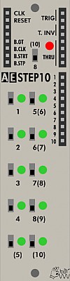
STEP10
This is a discontinued module and is no longer in production. It was replaced with the TRIQ164 Trigger Sequencer module.
Inputs
- Clock - trigger in to move the Step 10 to the next step. This can be from the Midi Clock, an LFO or any other +5V pulse (e.g. external sequencer)
- Reset - This puts the step count back to the first one regardless of previous position. Use for sequences other than 8 or 10 steps.
- B Gate - Midi Key on/off (external device via Master module)
- B CLK - Midi Clock (96 pulses per quarter note via Master module)
- B STRT - +5V pulse when Midi start is pressed (external device via Master module).*
- B STP - +5V pulse when Midi Stop is pressed (external device via Master module)
Outputs
- Trig (2) - +5V pulse with each switch that is on below.
- T. INV - +5V pulse with each switch that is off below.
- Thru (4) - Marked Mult on the original modules, passive signal splitter/mixer
Controls
- (10) 8 Switch - 8 or 10 steps in the sequence.
- 1-4 Switches - Steps 1 to 4 of sequence, trigger or rest depending on position and which output used.
- (5) Switch - Step 5 of a 10 step sequence
- 5 (6) Switch - Step 5 of an 8 step, Step 6 of a 10 step sequence.
- 6 (7) Switch - Step 6 of an 8 step, Step 7 of a 10 step sequence
- 7 (8) Switch - Step 7 of an 8 step, Step 8 of a 10 step sequence
- 8 (9) Switch - Step 8 of an 8 step sequence
- 10 - Step 10 of a 10 step sequence
This seems untidy on paper, but works well as bottom 2 switches are ignored in an 8 step sequence, rather than last 2 switches in right hand column if numbering was the same.
Patch Suggestions
As a 10 step sequence it is useful to provide variation to the usual 8 or 16 step sequences, whether triggering percussion, providing volume or filter modulation (direct or by triggering an envelope module), or even another sound/pitch. Its set output can be varied via attenuation in the 4ATT/Mix, 2ATT/CV modules etc.

STOMP I/O
With the STOMP-IO module, you can integrate guitar effect pedals and similar devices into your AE modular system! For output (send) and input (return) return there is a mono minijack socket; two minijack to 1/4" socket adapters are included as effect pedals usually work with the latter ones. Send and return levels can be controlled with separate knobs.
Front Panel Controls
- SEND - This controls the amount of the modular signal that is sent to the external effects processor (pedal)
- RETURN - This controls the amount of the return signal coming from the external device
Inputs and Outputs
- IN - Put a signal from the modular in here to be sent to the external effects processor (pedal)
- OUT - This takes the return signal from the external devices which you can now patch into further signal chain in your modular.
- MULT - there are 2 on this module, which are separate, one each side. These are passive splitters/mixers and very useful.
- SEND 3.5mmm socket - signal to go to the external device. Level controlled by knob above.
- Return - 3.5mm socket for the signal coming back form the external device. Level controlled by knob above.
Patch Suggestions
TW do provide 3.5mm to 6.35mm adaptors with this module, but cables with a different plug of these sizes on each end are readily available; less bulky at the AE end and, in theory, should be more reliable connection.
Obviously you can use any sort of pedal, but delays, flangers and phasers are particularly good with the AE.
Some users like distortion pedals, and this can be quite effective via the Stomp I/O as you can adjust the level to suit with the return knob. Running that distorted sound through a filter can be really good.
You can also use it to send a signal to an external synth, mixer or other device. The return can also be useful for bringing an external signal in as you can control the level with the return knob.
One immediate use found was the use of a bass synth pedal to boost the low end of the KICK module.
If you plug the 2 3.5mm sockets straight to each other, (lead not supplied), this module can be an attenuator, freeing up more complex modules for other duties.

SWITCHMATRIX 4x4
The SWITCHMATRIX 4x4 has four inputs and four outputs; via dedicated, iluminated buttons you can make freely every connection between these, no matter if CV or audio signals. Each routing / connection setting can be stored in one of 64 preset memories. Selecting the presets is possible by up/down triggers, CV, and of course by two up/down buttons.
A performance mode makes it possible to switch between 16 presets by simply pressing one of the matrix buttons - quite handy for live use!
Inputs
- IN 1..4 - Incoming signal, either trigger, gates or audio
- CV PRESET - Incoming CV from 0-5V selects one from 64 presets
- PRESET UP - incoming trigger selects next preset up
- PRESET DOWN - incoming trigger selects next preset down
Outputs
- OUT 1..4 - The outgoing signal depends on the button which connects an incoming signal with this outgoing one.
- Midi CTRL (on left hand side) - Midi Control Message from bus via Master module
- MULT - passive multiple
Controls
- 16x LED Buttons - These are arranged in a 4x4 grid and where a button is lit, that's where the incoming signal is routed to an outgoing one. In Performance mode, each of the 16 buttons selects one of presets 1-16. In Edit mode you can change connections by just toggling the buttons.
- PRESET + - this button selects the next preset.
- PRESET - - this button selects the previous preset
- SAVE/MODE - Pressing short once asks to save the current button combination to the preset that shows in the display, You can then select the preset and save with a second short press. Long press changes from Edit to Performance mode. In performance mode, pressing any of the 16 switches selects one of the first 16 presets. Long press again to return to edit mode.
Display
The LED display shows the current preset and mode.
Patch Suggestions
This module has many uses:
- as a performance switch matrix
- as a trigger sequencer
- for visual effects
It can be handy for quick octave changes, have the same modulation on 2 inputs but one is 1V higher (lots ways doing that - easiest is 2ATTCV module +5V switch and level adjust), then just switch when performing.
Using the preset up/down trigger inputs you can add or change sounds to a rhythm pattern....
This idea also works for extending sequences by running 2 sequencer modules, then have them switching from one to the other automatically:- see this thread:-
https://forum.aemodular.com/thread/1775/4x4-matrix-gives-bigger-sequencer
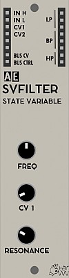
SVFILTER (STATE VARIABLE)
This filter module is a classic state variable filter.
Two signal inputs for different signal levels control the "drive" of the module.
Compared to the wasp filter this filter has a significant self resonance and also a very quick response to cutofffrequency changes.
Module power consumption: 2 mA
Inputs
- IN H - this input is for higher level signals.
- IN L - this input adds some gain to give a higher signal level of the module circuitry, (i.e. low input signals).
- CV 1 - control voltage for cutoff frequency, this will affect all three filter curves
- CV 2 - control voltage for cutoff frequency, this will also affect all three filter curves
Outputs
- LP - low pass filter output
- BP - band pass filter output
- HP - high pass filter output
- BUS CV - this sits below the input jacks on the left side and will output CV pitch from a connected MIDI device
- BUS CTRL - this sits below the input jacks on the left side and will output the MIDI control message from a connected MIDI device (CH1 - CC20)
Controls
- FREQ Knob - cuttoff frequency
- CV 1 Knob - control voltage attenuator
- RESONANCE Knob
Patch Suggestions
Here's a patch for a low pass gate:
- Any signal -> SVFILTER (IN L)
- SVFILTER (LP) -> VCA (IN1)
- ENV (OUT) -> SVFILTER (CV1)
- the same ENV (OUT) -> VCA (CV1)
This module does not have CV control of resonance, but it can be created by putting one of the filter outputs through a VCA whose level is controlled by the CV modulation source (e.g. LFO or envelope), then feeding the VCA output back into the same filter module - you may need a mixer module, or use a mult if necessary as the inputs have different levels. Try the low input for the feed back from the VCA first....
It can be interesting to combine the different outputs from the filter as they each create different sonic variation with the cutoff/resonance etc. This can be taken further by the different outs getting different treatment before being combined again. A good use for this is the Lo-Fi delay on the high pass &/or Bandpass filters to have a less "muddy" bottom end.
Sound Examples
AE Modular filter comparison: https://www.youtube.com/watch?v=ZY9VkSyMrik

TBD
The TBD module is a multifunctional DSP (digital signal processing) module that includes more than 30 different synthesis and audio processing plugins. It is a collaboration project between CTAG Kiel (an academic working group of Kiel University of Applied Sciences), Instruments of Things (who produce this module for Eurorack) and tangiblewaves.
Module power consumption: 80 mA
Plugin Documentation
There are over 30 plugins built in, these are effects, simple and complex sound generators. Some of these have over 20 parameters which you can control via the web interface. Here are the two main sources of documentation for these:
- Quick overview page with links to sections in the full documentation
- Full documentation of all included plugins
Inputs
- IN1, IN2, IN3 - All three inputs are being mixed together before passed into to the currently active plugin. This is used for audio input for FX plugins.
- CV IN 0, 1 - first and second CV input. These can be freely assigned to any plugin parameter via the web interface.
- TRIG IN 0, 1 - first and second trigger inputs. These can also be freely assigned to plugin triggers.
Outputs
- OUT - Audio output of the currently active plugin
Controls
- GAIN - Control the gain that is added to the incoming signal
- PAR 0, 1 - Potentiometer which can be freely assigned to any parameter of the currently active plugin via the web interface. These are independent from the incoming CV parameters.
- TRIG 0,1 - Trigger buttons which can be assigned to events of the currently active plugin via the web interface. These are independent from the other trigger inputs.
- CONFIG - allows the selection of a stored plugin. These are stored as "favorites" via the web interface and persist in the module even without a connection to a PC.
The Web Interface
You will need a computer (or Android device) which is connected to the TBD via USB to make the most of this module. The connection is made via a "terminal application"-program which you run on your computer and which opens a web interface on your default web browser. You can then control the TBD via this web interface.
The web interface runs on your PC as a local server and you open a web browser to "localhost:<port>" with port being any number greater than 3000. Commonly used ports are 3030 or 8080. Once you've opened the browser you see the start screen which shows you the currently active plugin(s) on the TBD which is connected to your PC. Downloading samples currently is not supported directly via the Webinterface, please use the "terminal application" for this instead.
If you run into issues compiling & updating samples, you may find this forum-thread helpful:

You can download the newest version of the "terminal application" here:
The Official Version for Windows already supports Windows 11 / The Legacy Version for Windows uses the same GUI as the one for MacOS
NEW: Android version
User @betaboon has kindly developed an Android application which works mostly like the above terminal application and can be installed on your Android phone or tablet. The connection is the same - just plug in a USB cable between the TBD module and your phone (you may need a USB-A to Micro-USB or USB-C adapter). Enable and serial connection and debugging when this question come up and then start the TBD app.
You can download the app from Google Play Store here: https://play.google.com/store/apps/details?id=com.aemodular.tbd
Patch Ideas
The 5th Volt has made this introductory video which will help you to get started with this complex module: https://youtu.be/tEKvm1mL8Fc
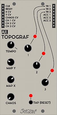
TOPOGRAF
TOPOGRAF is a drum sequencer with three tracks, that works with a "topographic" principle; it contains a number of drum patterns arranged in a "virtual map"; and with two knobs MAP X and MAP Y you can set a position in this map. With one knob per channel the density is defined; and a CHAOS knob brings some randomness into the whole process. All in all a few knobs for a lot of drum patterns you probably wouldn't make this way by yourself - a nice source of inspiration and alo great for playing live.
TOPOGRAF is the AE modular version of the Grids module by Mutable Instruments. It is 100% identical to Grids. The user manual for that module can be found here. https://mutable-instruments.net/modules/grids/manual/
Module power consumption: 20 mA
Inputs
- CLK - this is a trigger input, you will need a divider module to control via midi clock and the Master module, see also advanced settings/modes below.
- Reset - Sets back to step 1 of the trigger sequence being played, and keeps sync with other triggered items if needed.
- X CV - In most cases this would be the trigger pattern over the steps of the "sequence" for track 1, although really it does more than this... Combined with the Map X Knob position.
- Y CV - In most cases this would be the trigger pattern over the steps of the "sequence" for tracks 2 and 3, although really it does more than this... Combined with the Map Y Knob position.
- Chaos CV - This will affect the amount of randomness in the Topograph's outputs depending on its level.
- CH 1 CV - This is combined with the Knob 1 position for the amount Output 1 will be triggered in the pattern.
- CH2 CV - This is combined with the Knob 2 position for the amount Output 2 will be triggered in the pattern.
- CH3 CV - This is combined with the Knob 3 position for the amount Output 3 will be triggered in the pattern.
To understand these inputs more clearly the Grids manual is recommended.
Outputs
- TR 1 - Track 1's output, the pattern is dependent on the X,Y setting, and the amount of triggers in the pattern are set by the CH1 CV and Knob 1.
- TR 2 -Track 1's output, the pattern is dependent on the X,Y setting, and the amount of triggers in the pattern are set by the CH2 CV and Knob 2.
- TR 3 -Track 1's output, the pattern is dependent on the X,Y setting, and the amount of triggers in the pattern are set by the CH3 CV and Knob 3.
- ACC1 - Extra trigger(s) on track 1 dependent on the pattern being used, (X,Y setting).
- ACC2 - Extra trigger(s) on track 2 dependent on the pattern being used, (X,Y setting).
- ACC3 - Extra trigger(s) on track 3 dependent on the pattern being used, (X,Y setting).
Controls
Detailed explanations of the various controls are given in this video.
- RATE - if no external clock is given in CLK then this knob controls the clock rate of the sequence
- MAP X - selects the X position on the map of patterns
- MAP Y - selects the Y position on the map of patterns
- CHAOS - adds randomness to the pattern. Turn right for more randomness.
- FILL 1 - 3 these control the fill of triggers for each track. Turned completely anti-clockwise will mute that track.
Advanced Settings and Modes
The Topograf has the exact same program as MI Grids and the manual for Grids (see above) can be used. However here is a detailed explanation of the different advanced settings and modes.
Changing the clock resolution
You can change the clock resolution on the Topograf like this:
- unplug all CV and hold the TAP (RESET) button for a second to put the Topograph into advanced settings mode
- the FILL1 knob changes the clock resolution which you can as a pattern on the 3 LEDs
- 4ppqn = first LED is on
- 8ppqn = second LED is on
- 24ppqn = third LED is on
- Turn the FILL1 knob to select the resolution you want
- Hold the TAP (RESET) button again for a second to save the settings
You can experiment with 4 or 8 ppqn, but 24 ppqn is usually only useful if you want to clock the TOPOGRAPH directly from the MIDI bus.
The following video explains the advanced configuration options. https://youtu.be/GLRYptx4Zmg
Patch Suggestions
Gaetan from the forum suggests:
Example for a bass line
- Trigger the envelope generator of your voice with the topograph's kick
- Patch the same kick trigger to your SEQ16 clock
- Patch the SEQ16 to control the pitch of your bass line
Now, every time topograph sends a kick, your sequence will advance one step.
More fun
- AND together the kick and snare, and use them to trigger your voice's EG
- Use the hihat to clock the SEQ16
You're going to have some pretty groovy bass lines with that
Or for a melody
- Clock your SEQ16 with a regular clock, and send the output to a Sample & Hold
- AND the HH and the kick, and use it to trigger both your voice's EG and the S&H
- Use the output of the S&H as you voice's pitch
You'll have a stable melody that will skip steps according to the state of the Topograf

trip
TRIP
TRIP is a TRIgger Processor module; it takes incoming triggers and repeats them - you can think of it as a delay module for triggers. The delay time and the number of repeats can be set with a knob and additionally be CV controlled. Beyond a static delay, the delays of one input trigger can be accelerated or decelerated, leading to the rhythm of a bouncing ball for instance. In another mode, the probability of the output triggers can be chosen.
Different output modes change the assignment of the delays to the eight outputs; either, all delayed triggers for one input trigger are on one output, or the delays go through the outputs 1...8. By this, complex events can be triggered.
Finally, the acceleration and the gate time can be CV controlled as well.
The module is "polyphonic" in a sense, that consecutive triggers at the input don't stop currently running trigger outputs from a previous trigger, but mixing them all. Together with variable delay times and acceleration, highly complex trigger patterns can appear on each of the eight outputs.
Module power consumption: 8 mA
Inputs
- TR IN - trigger input
- DELAY - accept CV for the delay time (value from knob DELAY TIME will be added)
- RPTS - accept CV for number of repeats (value from knob REPEATS will be added)
- ACCEL - accept CV for acceleration (value from knob ACCELERTN will be added)
- GATE - accept CV for gate time (value from knob GATETIME will be added)
- MUTE - silences all outputs
Outputs
- 1...8 - trigger outputs;depending of seleted operation mode
Controls
- DELAY TIME Knob - change the delay time from 0.02 to either 1 or 5 seconds depending on FAST/SLOW operation mode
- REPEATS Knob - change the number of trigger repeats from 1 to 32
- ACCELERTN Knob - change the acceleration (center to right) / deceleration (center to left) of the delayed triggers
- GATE TIME Knob - change the gate time of the output triggers
- PROBABL./ACCEL. Switch - switch between PROBABILITY or ACCELERATION mode. When in ACCELERATION mode, the outputput triggers will fire faster / slower with every step; when in PROBABILITY mode the output triggers are fired/supressed randomly.
- MAN TRIG Button - sends a trigger signal to start the triggers manually, additionally to the TR IN.
Configuration
Pressing the MAN TRIG button for one second enters the configuration mode; here:
- the LEDs 1..3 show the output mode; change with knob DELAY TIME
- the LED 5 shows the dry+wet mode; change with knob REPEATS
- the LED 6 shows the delay time range; change with knob ACCEL
- the LED 7 shows the overflow mode; change with knob GATE TIME.
Output modes:
Mode 1 is a combined mode; output 1 has all delayed triggers, outputs 2-8 have only the delayed trigger of the according delay counter. If REPEATS is greater than 7, then the outputs 2-8 remain silent for later delays.
Mode 2 is similar to Mode 1, except that the combined triggers at output 1 don't exist, therefore you have 8 separate outputs for the delays 1 to 8.
Mode 3 works as following: The delays of the first input trigger appear at output 1; if a new input trigger signal comes in before the first delayed trigger sequence is finished, then it's delays are sent to output 2. Same for subsequent trigger inputs up to eight. For further trigger inputs it is checked which output is free (no more current triggers running) and this one is used for the delays of the incoming trigger.
Dry+Wet mode:
When Dry+Wet mode is activated (LED 6 in Configuration mode), then the input trigger is also sent to the output, so original trigger and it's delays are combined.
Delay time range:
When the time range is set to on (LED 7 in Configuration mode), then, the maximum delay time range is eight times longer compared to time range "off". The maximum delay time is approx. 20 seconds, and even longer with negative acceleration.
Overflow loop:
When the overflow loop is set to on (LED 8 in Configuration mode), repeats that exceed the count of 8 are started again within the output range of eight outputs. If set to off, then repeats (except output 1 in Mode 1) beyond the 8th are discarded. This setting has no effect in Mode 3.
Quit the configuration: Short pressing the MAN TRIG button exits the Configuration mode and returns to regular operation.
Patch Suggestions
The most obvious use for this module is "echo" type FX, repeating a sound as set by the module controls.
It can be good on CVs, try it off an LFO going to filter cutoff....
An excellent module for helping produce sound FX, try NOISE through a VCA controlled by this module as a starting point.
Most people run this module from an LFO to provide the initial trigger, but there's no reason it can't be one of the AE modular's sequencer clocks or trigger outs... This can be excellent to then provide a modulation source that (sort of) works with the tempo.
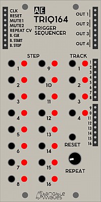
TRIQ164
TRIQ164 is designed as improved replacement for the STEP10.
TRIQ164 is a 4-track trigger sequencer. It can have a maximum of 16 steps and all tracks have to be the same length. All 4 run in sync but a single track is on the front panel at any one time, switched by the Track buttons. A trigger sequence means it cannot generate CVs for, e.g., pitch but does a +5V pulse when a step is selected to be active. Excellent for controlling percussion sounds, e.g. Drumkit 010 module.
Width: 2U
Module power consumption: 6 mA
Inputs
- CLK - accepts trigger to advance one step
- RESET - go back to step 1
- MUTE1 - accept gate to mute OUT 1. Mutes signal when input is HIGH.
- MUTE2 - accept gate to mute OUT 2. Mutes signal when input is HIGH.
- REPEAT CV - control voltage for adding repeated triggers within one step, please see repeat knob below.
Outputs
- OUT [1-4] - outputs for each track. The value is given by the current step of the corresponding track.
- [1-16] - trigger output for each step of the currently selected track only. NOTE: Repeats are not available through these outputs
- B. CLK - MIDI clock via the Master module
- B. START - +5V trigger pulse when MIDI START is sent from external equipment, via the Master module.
- B. STOP - +5V trigger pulse when MIDI STOP is sent from external equipment, via the Master module.
Controls
- TRACK Buttons [1-4] - select the track to be edited. The LED by each track button represents the output signal of that track, i.e. steady on LED means that track is selected. When that numbered track has a trigger on that step of the sequence, it will flash. Also makes the individual step outputs available
- STEP Buttons [1-16] - activate/deactivate steps in the current track only. The LED by each step button indicates if the step is active (ON) or inactive (OFF) in the current track only. NOTICE: The same step my have different values in different tracks
- RESET Button - resets the sequences (jump to step 1)
- REPEAT Knob - select the number of repeated triggers within one step, (i.e. ratcheting). From no repeats (turned all the way to the left) to 8 repeats (turned all the way to the right). To assign a step to repeat, hold the track button and push the step(s) you want to have in repeat mode. You must turn the knob to the right to get repeats on the assigned step(s), or put a voltage on the repeat CV in. If the knob is at zero position and you have no CV you will not get any repeats.
Patch Suggestions
For sequences shorter than 16 steps, connect a step output to RESET. For example, if you want a 4-step sequence, connect STEP OUTPUT PIN 5 to RESET.
You can use a TRIQ164 channel to trigger the clock on the SEQ16 or SEQ8 modules so you can do different rhythms/ time signatures with them around your master tempo clock going into the TRIQ164.
As with all AE modules, it can be "abused" - (AE does stand for Abused electronics!), with a high clock rate it can become an audio FX generator or processor. please see the thread on the forum
https://forum.aemodular.com/thread/1595/triq164-module?page=1&scrollTo=13144
Here is a video by The 5th Volt which explains how to use the TRIQ164: https://youtu.be/HrwxXI29Ack

TUBE-VU
Please note that this module must have a separate 9V power supply to the rest of your AE system, hence the socket on the front! TW do sell one here.
A brilliant module for people who use their AE live.
Input
- 1 - Input for circuit 1
- 2 - Input for circuit 2
- MULT - a passive mixer/splitter completely separate to the module electronics.
Output
There are no outputs, as the tubes would produce too higher voltages for the rest of the AE system.
Control
-
Level 1 knob - set the level for circuit one so you get the best display...
-
Level 2 knob - set the level for circuit two so you get the best display...
-
R knob - sets the amount of red in the colour of the tubes.
-
G knob - sets the amount of green in the colour of the tubes.
-
B knob - sets the amount of blue in the colour of the tubes.
These last three "knobs" are actually small trimmer pots so you may need a tool to adjust carefully.
Display
The reason to buy this module!
The left tube displays the status of circuit 1, right circuit 2.
The brighter the tube the louder the signal...
Patch Suggestions
The main reason for 2 circuits in this module is so you can do stereo, but it can be really good to have 2 different sounds so the Tubes vary individually.

µ2MIX
This 1/2 height micro module provides a tiny mixer with 3 attenuated channels and 4 fixed channels.
This module needs to be installed on the µBASE module!
Module power consumption: ? mA
Inputs
-
IN A1, A2, A3 - These are inputs to the attenuated (via the pots) channel of the Mixer
-
IN A3b - This input will be mixed together with input 3 and attenuated at the same time
-
IN B1, B2, B3, B4 - These inputs are mixed together without manual attenuation, however by choosing to insert via the 1.0 or 0.3 inputs you can add the signals either at full or a third of their strength.
Outputs
- OUT A Mix from attenuated mix inputs (A)
- OUT B Mix from unattenuated mix inputs (B)
Controls
- A1, A2, A3 Pot - Volume attenuation of the channels 1 - 3
Patch Suggestions
This can be used for Audio or CV mixing of signals and is very similar to the MIXER 4-4 module.

CVSHIFTER
The CVSHIFTER module controls 4 outputs from one CV input; what the outputs do depend on the mode the user chooses.
- Classic - Each trigger in shifts the CV out by one position, the new CV goes to output CV 1. The CV that was at output 1 goes to output 2 and so on. This means you need to have 4 triggers before there is a CV at output 4. This mode will not produce triggers at the TRIG 1-4 outputs. This mode means you can generate chords within your AE modular.
- Cycle - Each trigger sends the CV to the next output channel with a gate signal at the relevant output, after output 4 it cycles back to output 1. This can be excellent for percussion tracks.
- Random - The CVs are sent in random order to one of the four outputs, with a gate at the relevant output.
Power Consumption: 12 mA
Inputs
- CV - the input CV which is sampled with each trigger pulse
- TRIG - the trigger input which samples the input CV and sends the output to one of the outputs
- TRIG SLOW - ?
- RESET - reset the sequence
Outputs
- CV1 - The first output of the sequence
- CV2 - The second output of the sequence
- CV3 - The third output of the sequence
- CV4 - The fourth output of the sequence
- TRIG1 - When in CYCLE mode this sends a trigger on the first step of the sequence, in RANDOM mode, when output 1 is selected.
- TRIG2 - When in CYCLE mode this sends a trigger on the second step of the sequence, in RANDOM mode, when output 2 is selected.
- TRIG3 - When in CYCLE mode this sends a trigger on the third step of the sequence, in RANDOM mode, when output 3 is selected.
- TRIG4 - When in CYCLE mode this sends a trigger on the fourth step of the sequence, in RANDOM mode, when output 4 is selected.
Controls
- MODE - cycles through the 3 modes explained above.
- RESET - performs a manual reset of the sequence, so the next CV will be on output 1 only.
- MAN TRIG - manual trigger for a CV sample/next step in the sequence.
Display
The 4 leds light when the relevent output has a CV present.
Patch Suggestions
Compared to the "classic" circuits, this module is digital based and therefore doesn't suffer from drift as some analogue ASRs and S&Hs do. The result is, that you can control the pitch of up to four oscillators which can be a move into polyphony. The first step is to do a paraphonic synth, which means the four oscillators go through one filter and VCA. If you have a keyboard connected to your AE, the Key CV (BUS CV if using a midi keyboard) and trigger (BUS GATE if using midi) need to go to the CVShifter inputs; experiment from there!
This module can be excellent for producing CVs that are used to modulate a sequence; you can run the triggers so that they are triggered every step of the sequence (e.g. using the out on the SEQ8), a specific step using the numbered outs or, where it can get really interesting, is using one of the 4 sequences in the TRIQ164 or Euclid Grid....
DELAY (LOFI TYPE)
Lo-Fi Delay is a analogue, old fashioned bucket brigade style of delay
Module power consumption: 18 mA
Inputs
- In - Main incoming audio signal
- CV - CV control of delay time so can do Flanger/Phaser type sounds (with LFO).
- In 2 - for 2nd signal in, this will be mixed in without attenuation
- In 3 - for 3rd signal in, this will be mixed in without attenuation
Outputs
- Outs (2) - (mixed signal)
- Wet- (delay sound only)
- Dry - (original signal(s) only)
- Thru - passive mixing/splitting nothing to do with the delay.
Controls
- Delay - Set delay time, further impacted by CV control above.
- Feedback - This controls the amount of the output signal that is send back to the input, so you can get reverb type sounds, repeated echoes etc.
- Dry/Wet - This controls the amount of dry (original signal) and wet (the delayed sound) in the output.
Patch Suggestions
Dynamic Control If you want dynamic control of the dry/wet mix, you can use the separate outs and then combine in the 4ATT/Mix or 4VCA.
Bass Sounds Excellent on bass sounds as is naturally less bright than digital delays.
CV Control Using the CV control of the delay time can be done with any CV, not just LFOs. Sequencer CV outs can generate some great rhythmic and/or melodic effects. Envelopes can the same, or do strange FX depending on settings and how they are triggered.
Other input sources It can be really interesting on CV rather than audio.....
Controlling Feedback The wet signal output and the three mixed inputs makes adding CV control over feedback straightforward. Simply run the wet output to the signal input of a VCA, and run the VCA output to one of the delay inputs. The VCA CV input now controls the amount of feedback. Use a module like the CV Tool to add an offset and attenuate a CV from an LFO or envelope in order to more precisely control the feedback.

DIODEFILTER
The DIODEFILTER is an adaption of the well-known diode ladder filter that became most popular by Roland's TB-303 bassline. And here it is for the AE modular!
Module power consumption: 3 mA
Inputs
- In H - Input for lower level signals
- In L - Input for higher level signals
- CV1 - 0-5V control voltage input whose effect level is controlled by the CV1 knob.
- CV2 - 0-5V control voltage input, with no controlled attenuation within this module.
- Accnt1 - Boosts the filter cutoff/volume when a voltage is applied.
- Accnt2 - Boosts the filter cutoff/volume when a voltage is applied.
Outputs
- LP OUT (x2) - The audio signal after being filtered.
- Bus CV - Voltage produced via a midi keyboard connected to the master module.
- Bus CTRL - Voltage produced via a midi keyboard connected to the master module.
Controls
- FREQ - Sets the Cutoff Frequency of the filter
- CV1 - Controls the amount the CV1 input affects the cutoff frequency of the filter.
- RESONANCE - the more this level is increased the more the frequencies around the cutoff frequency are enhanced/ amplified.
Patch Suggestions
It shouldn't really need saying that this is a great filter for bass lines! Try Sawtooth and PWM waveforms for the most obvious effect....
Having an LFO not synced with the tempo, KK's sloth or even a envelope on a slow trigger to vary the cutoff frequency (from gentle to mad!) is great, especially on bass....
This module does not have CV control of resonance, but it can be created by putting one of the filter outputs through a VCA whose level is controlled by the CV modulation source (e.g. LFO or envelope), then feeding the VCA output back into the same filter - you may need a mixer module, or use a mult if necessary as the levels on the 2 inputs are different. Try the low input for the feed back from the VCA first....
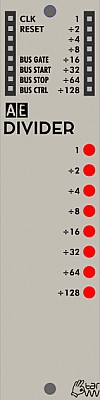
DIVIDER
This module is discontinued. The Beat Divider does a similar role. The MM Divider is its more versatile direct replacement in a lot of ways, but this divider is well worth keeping, as it is a simpler device for beats, and also can be used on audio signals with great results.
Inputs
- CLK - the clock signal you want to reduce with this module.
- Reset - this input is used to reset the divider module to keep in sync with the provided clock.
Outputs
These 4 are on the left, usually input side of the module.
- Bus CLK - Midi clock from a connected Midi device (via the Master module). erroneously labelled Bus Gate on some modules (as illustrated)
- Bus Start - +5V pulse when a connected Midi device start key is pressed.
- Bus Stop - +5V pulse when a connected Midi device stop key is pressed.
- Bus Ctrl - a CV based on Midi controller No. 20 (CC20) of a connected Midi device.
On the right side of the module:-
- 1 - a straight copy of the input.
- 2 - a half speed copy of the input.
- 4 - a quarter speed copy of the input
- 8 - output is an eighth the speed of the input.
- 16 - output is a sixteenth of the speed of the input.
- 32 - output is a 32nd the speed of the input.
- 64 - output is a 64th the speed of the input.
- 128 - output is a pulse for every 128 pulses of the input.
Controls
None.
Patch Suggestions
The most obvious is to reduce the 24 pulses per quarter note of the midi clock signal down to something more useful for triggers within the AE modular. You will need the Midi clock from an external source via the Master module.
Please see the other divider modules for further ideas
DIY Kit
There are no boundaries with this module! You decide what inputs, outputs and controls it has. You also design the circuit for what you want the module to do. There are ideas and some circuits designs on the forum, see the DIY section
https://forum.aemodular.com/board/8/diy-building
https://forum.aemodular.com/thread/1402/diy-kit-module-project-suggestions
The photograph above shows the parts included in the kit so your project can fit in the AE format.
The schematic of the DIY module: Attach:DIY-module-schematic.pdf
If you are interested in building your own circuits/modules you should also look at the braedbaord module.
https://wiki.aemodular.com/pmwiki.php/AeManual/BRAEDBOARD
Enjoy your time down the rabbit hole.....

DRONE38
DRONE38 is a sound generator with 18 oscillators in total, organized in six groups of three oscillators each. 12 of them can be switched between sawtooth and triangle waves, 6 are fixed sawtooth oscillators.
The groups can be mixed individually with 3 mixer knobs, where each 2 groups can be assigned to the level. Additionally, each group can be activated / “played” with buttons near the group.
The oscillators are not meant to be controlled by CVs, but only set static with a knob. By mixing them, very dense drones and clusters can be created.
Additionally, 6 oscillators can be synced to other ones for extending the sonic palette.
Module power consumption: 6 mA
Inputs
- A1 - A6 SYNC - You can patch from the outputs B1 to B6 into these to synchronise A and B banks.
Outputs
- OUT - The mix of all banks, taking into account the section on/off switches and bank level knobs.
- SUM A - the mix of all oscillators in bank A, taking into account the section on/off switch, but not affected by the bank A level knob
- SUM B - same for bank B
- SUM C - same for bank C
- Pulse Outputs B1 - B6 - Patch these into the inputs A1- A6 to sync the A and B oscillators
Controls
- PITCH A1-A6, B1-B6, C1-C6 - these control the individual pitches of the oscillators
- Trigger Button A1-3,A4-6, B1-3, B4-6, C1-3, C4-6 - when pressed these momentarily activate the respective section even when it is switched off with the section on/off switch
Patch Examples
It is designed to be used with the Dronx Mixer/FX module but does not have to be. The Mixconsole is also an option, or a 4VCA module or two...
There is a video by the 5th Volt...

DRONX
This is a 6 channel mixer, with tone controls and built in delay FX. It is optimised for use with the Drone38 module but is useful for larger AE systems regardless.
Another possible mixer is the Mixconsole.
Module power consumption: 42 mA
Inputs
-
IN1 to IN6 Channels 1 to 6 for the mixer, level controlled by the relevant vertical fader (below)
-
TIME1 CV this combined with the time 1 knob controls parameter 1 of the in built FX chosen.
-
TIME2 CV this combined with the time 2 knob controls parameter 2 of the in built FX chosen.
Outputs
- OUT (x3) - mono output of the Dronx module.
- MULT - a passive splitter/mixer separate to the module electronics.
Controls
- Bass - alters the level of lower frequencies in the mixed signal
- Treble - alters the level of higher frequencies in the mixed signal
- Distortion - depending on your point of view, this sets the level of analog authenticity or racket!
- Time 1 - sets the delay time of channel 1 of the selected FX.
- Time 2 - sets the delay time of channel 2 of the selected FX.
- LFO depth - this controls the amount the LFO affects the sound, the rate is set by the selected program.
- Feedback - with no feedback you only get the original sound going through the FX once, with maximum feedback it goes through an infinite number of times; somewhere in the middle is usually great musically, this knob controls the amount...
- DRY - WET - A fully dry signal has none of the FX sound in it. A fully wet signal is just the FX sound. Again, we usually want somewhere in the middle which is controlled by this knob.
- Level 1 to Level 6 - controls the amount of the signal from that numbered input in the output signal.
Delay Effect Programs
The delay FX unit of the DRONX has 9 unique programs that are described below:
- single short
- single long
- echo 1 (two delays with different feedback levels)
- echo 2 (two delays with different feedback levels)
- echo 3 (two delays with different feedback levels)
- parallel delays
- chorus + delay (with LFO modulation, depth with LFO DEPTH, speed is fixed)
- wonky (like 3 but random modulation delay time, depth with LFO DEPTH)
- glitch (like 8 but at the beginning and end of the delay times the delay chip is being "abused" to generate weird and unexpected effects)
Patch Examples
Even if you do not have 6 sound sources in your AE system this still is a useful module, if you can spare the real estate!
Most AE VCOs let you use more than one output at once, so this can be used as a sub mixer for them before further processing (with or without FX).
You can use it to mix parts from different areas along the audio chain, e.g. before and after the Filter.
It is useful to combine external sources (via 4I/O module), drums (e.g. Kick module) and VCOs, Solina module etc. to make one output to send to your recording device/PA etc.
Here is a video made by The 5th Volt about the DRONE38 and DRONX modules: https://youtu.be/bkpZkUtRAy4
DRUMKIT 010
The DRUMKIT 010 consists of 11 8-bit drum sound samples; 6 of them can be triggered in parallel in any combination by the trigger inputs.Don't expect high quality from this module - it's by design a nasty, lo-fi drum sound source, but definitely with its own character. Works great together with the analog KICK module.
Module power consumption: 3 mA
Inputs
- BD - trigger for bass drum
- SD - trigger for snare drum
- CP - trigger for clap
- CH - trigger for closed hi-hat
- OH - trigger for open hi-hat
- FX - trigger for FX sound
- PITCH CV - cv control of pitch for all sounds
- ACCENT - trigger for accent
Outputs
- OUT - audio output of mix of all sounds
- MULT - unbuffered multiple
Controls
- BANK Knob - select a bank of sounds, this selects different sounds for the 6 channels. Because there are only 11 sounds in total, each bank is a different mix of 6 of those sounds.
- PITCH Knob - select the pitch of all sound samples
- REVERSE Button - while pressed, all samples will play in reverse
- TRIG MODE Switch - if set to A any rising signal will trigger, if set to D a short pulse is expected.
Patch Suggestions
The DRUMKIT works best when triggered by either the TOPOGRAF, TRIQ 164 or MM-DIV modules.
Some older versions of this module are a bit low in volume, so patching the output through the 2SIGNALAMP will boost the signal to be on par with other voices in the system.
One of the great things you can do within modular is combine sounds; this module can be used to put an a noise on the attack part of a sustaining sound from a VCO; Roland D50 Sound and Synthesis for 10% of the price!
The drum sounds from this module can, of course, be processed by the rest of your AE system; Lo-fi delay, Filters and Kurt's Deadband are highly recommended.
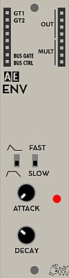
ENV
This module is discontinued, replaced by the 2ENV module.
An attack/decay envelope generator with a sustain on/off switch.
Inputs
- GT1 - Main trigger input, +5V pulse will trigger the Envelope cycle.
- GT2 - Secondary trigger input, +5V pulse will trigger the envelope cycle.
Outputs
The first two are on the usual input side of an AE module.
-
Bus Gate - Gate is on when a midi note is held, via Master module.
-
Bus Ctrl - Value of Midi CC20 controller via Master Module.
-
OUT (4) - the Envelope CV value.
-
Mult (4) - a passive mixer/splitter with no connection to the module's circuits.
Controls
- Gate Hold On/Off switch - when on, +5V will be at the output until the trigger is released. When off the envelope will go through its attack/decay cycle without pause, holding a trigger will not affect the envelope.
- Fast/Slow switch - Affects the rate at which the envelope changes over time, fast is best for percussion.
- Attack knob - sets the rate at which the CV rises from zero when the module is triggered.
- Decay - sets the rate at which the CV drops to zero when the trigger stops, would be called release on a standard ADSR tyre envelope.
Patch Suggestions
Though the new 2ENV module is superior, this is still a useful module. It is very good for percussion, or putting a "brightness" on a sound when triggered (by modulating the filter in addition to whatever modulation you are using).
It provides an non-LFO modulation source which can be inverted with use of the Logic module (so you have a dropping voltage with attack, and rising with decay), this can be good on pitch modulation (subtly!) to sound more like an acoustic instrument.
The main reason to replace this module with a 2ENV would be space; you get 2 separate envelope circuits in the same module. The 2ENV also has CV control inputs for Attack/Decay, trigger buttons and, best bit, an LED that lights up when the envelope circuit is triggered.
This video by Synths & Things explains the ins and outs of this module really well: https://youtu.be/CfxyHNwQUkc

ENVFOLLOWER / EXT IN.
The ENVFOLLOWER/EXT.IN module brings external sound sources into your AE modular; it does this in different aspects:
The module has two mono audio inputs for external sources; one unbalanced for line level signals like audio players, tapes, portable recorders, and a balanced one for directly attaching microphones (dynamic and self powered condenser mics, but not phantom powered ones). This input signal is brought then to AE level.
Now, from the input signal an envelope is derived, giving the volume of the signal as CV which can control what you want, e.g. filter cutoff, pitch or what else is CV controllable within your AE system. The SMOOTH knob controls the shape of the envelope/suppression of the audio signal component.
Finally, the ENVFOLLOWER module provides a gate signal, indicating that the level of the audio input is above a certain level that can be set with the GATE THRES knob.
Power Consumption: 7 mA
Inputs
- IN - This patch point at the top left of the module accepts audio input coming from within the AE system, eg. from a VCA.
- UNBAL. IN - 3.5mm mono input for line level signals, eg. from audio players, recorders, PC or other synths
- BAL. IN - 3.5mm mono input for microphones, dynamic or self powered condenser mics. Does NOT provide phantom power.
- Mult - a passive mixer/splitter completely separate to the module circuits.
Outputs
- ENV (x3) - CV signal which follows the amplitude of the incoming signal.
- GATE (x3) - Gate which is on when the audio level is above a certain threshold
- SIGNAL (x2)- Duplication of the incoming audio signal. If coming via the balanced input, the signal has been raised to AE level.
Controls
- GAIN - controls the level of the incoming signal before processing, in general it is best to be as loud as possible without distortion, (Clipping).
- SMOOTH - controls how smooth or jagged the resulting env signal is from the audio, in the same manner as a slew generator.
- GATE THRESH - controls the threshold at which the GATE output is on.
Display
- CLIP - lights if the incoming signal is (getting) too much for the module circuitry.
- ENV - lit when there is a CV at the ENV output
- GATE - lit when the gate output is high/activated.
Patch Suggestions
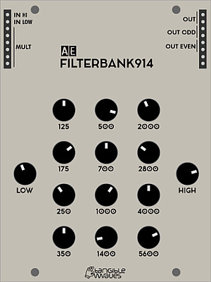
FILTERBANK914
This is a recreation of the famous Moog filterbank module.
Module power consumption: ? mA
Inputs
- IN -
Outputs
- OUT - output
Controls
- LEVEL knob -
Patch Suggestions
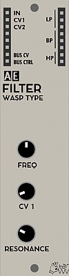
FILTER (WASP TYPE)
This filter module is a variant of the Wasp filter, a quite strange circuit used first in the EDP Wasp synth end of the seventies, which abuses digital chips in an analog way leading to the characteristic sound of this filter type. In this module, vactrols are used for controlling the filter frequency.
NOTE: This module has been upgraded. Version 1 has only one signal input (IN), while version 2 has two signal inputs for high-pass and low-pass. See inputs.
Module power consumption: 3 mA
Inputs
- IN - (v1 only) audio signal going through the filter
- IN H (v2 Only) - this input is for higher level signals.
- IN L (v2 Only) - this input adds some gain to give a higher signal level of the module circuitry, (i.e. low input signals).
- CV 1 - accepts CV control for cutoff frequency, this will affect all three filter curves
- CV 2 - additional CV control for cutoff frequency, this will also affect all three filter curves
Outputs
- LP - low pass filter output
- BP - band pass filter output
- HP - high pass filter output
- BUS CV - this sits below the input jacks on the left side and will output CV pitch from a connected MIDI device
- BUS CTRL - this sits below the input jacks on the left side and will output the MIDI control message from a connected MIDI device.
Controls
- FREQ Knob - cuttoff frequency
- CV 1 Knob - control voltage attenuator
- RESONANCE Knob
Patch Suggestions
Here's a patch for a low pass gate:
- Any signal -> WASP (IN L)
- WASP (LP) -> VCA (IN1)
- ENV (OUT) -> WASP (CV1)
- ENV (OUT) -> VCA (CV1)
This module does not have CV control of resonance, but it can be created by putting one of the filter outputs through a VCA whose level is controlled by the CV modulation source (e.g. LFO or envelope), then feeding the VCA output back into the same filter module - you will need a mixer module, (e.g. 4ATTMIX), or use a mult if necessary as there is only one input.
Sound Examples
This video below shows a comparison between the AE Modular WASP filter and the original. https://youtu.be/kGIT-D9sueo
AE Modular filter comparison: https://www.youtube.com/watch?v=ZY9VkSyMrik

FMOS
The FMOS brings FM synthesis to the AE modular. It offers the basic FM synthesis with one oscillator and one modulator, which can be either sine wave or triangle wave independently. The modulation depth and frequency ratio of the modulator can be set with a knob and additionally by CV control. It can also produce a sine wave if needed.
Module power consumption: 30 mA
Inputs
- CV1 - CV control over the pitch of the oscillator.
- CV2 - CV control added the CV1 to control the pitch.
- MLT CV - CV control over the FM frequency ratio of the modulator.
- DPT CV - CV control over the depth of the modulator's depth.
Outputs
- OUT - audio output signal
- B.CTRL - CTRL signal from MIDI bus
- B.CV - CV signal from MIDI bus
Controls
- Switch triangle/sine - switch between triangle or sine waves of both carrier and modulator.
- PITCH - Potentiometer for changing the pitch of the oscillator. When CV is sent, then that will be added to this setting.
- Switch +2OCT - When in high position, the pitch will be increased by 2 octaves
- MULTIPLIER - Potentiometer to select the FM frequency ratio. Any CV control will be added to this setting.
- MOD DEPTH - Potentiometer to select the depth of the modulation. Any CV control will be added to this setting. Turn it all the way to the left (set to 0) for pure sine wave.
Patch Suggestions
FM synthesis lends itself to bell sounds in particular, and brings a whole different colour palette to regular oscillators. Very useful for percussion also.
FMOS lends itself to be used as the main oscillator in a patch. One famous patch where a FM-type of oscillator got used is the Krell patch by Todd Barton on a Buchla.
A version of the patch you can rebuild with the AE Modular is described here: http://manual-synthesis.info/2017/01/26/krell/#fn:1
The full details of the patch used with AE Modular are to be found here https://forum.aemodular.com/post/7208/thread
Any settings of FMOS can make sense in that context and should be done to your liking.
The sine wave can be really good as a modulation CV, usually attenuated with a 2CVTOOL or similar.
Here is a video by The 5th Volt which features this module.

GRAINS
GRAINS is a programmable multipurpose module that has first been developed by Ginkosynthese for Eurorack. The AE Modular version is 100% compatible with the source code for the original, but there are a few added features. It is based on the Atmega 328 micro controller, well known as the core of the Arduino Uno, Nano and other boards, and can act as a granular sound player as well as different other functions depending on the firmware. It can be programmed directly by the Arduino IDE via the integrated USB socket on the front side of the module via the included USB cable.
The newer revision of this module has a switch to enable the use of the open source Mozzi Library which makes programming much easier.
The module comes with the WAVEGRAINS firmware pre-installed which is a wavetable oscillator that is immediately useful. However you can install other firmware quite easily as described below.
Module power consumption: 12 mA
Inputs
- IN1 - accepts a CV signal
- 2 - accepts a CV signal
- 3 - accepts a CV signal
- A - accepts an audio signal (this is a new feature of the AE Grains and isn't available on the original Eurorack module)
Outputs
- OUT - This is an audio signal direct from the PWM output pin of the Atmega chip running through a lowpass filter
- D - This is a digital signal that can be used for triggers, etc. (this is also a new feature and does not exist on the original Eurorack module)
- MULT - unbuffered multiple, unconnected from the module's circuitry
Bus outputs on the left hand bank of sockets.
- Bus CV - CV signal from MIDI
- Bus CTRL - Gate signal from MIDI
- Bus Gate - Gate signal from MIDI
Controls
- Pot Level 1 - depending on switch 1 attenuate signal from IN1 or select CV level between 0-5V
- Switch IN1/MAN - switch between attenuating signal from IN1 or issue CV between 0-5V (the original Eurorack module does not have this switch)
- Pot Level 2 - depending on switch 2 attenuate signal from IN2 or select CV level between 0-5V
- Switch IN2/MAN - switch between attenuating signal from IN2 or issue CV between 0-5V (the original Eurorack module does not have this switch)
- Pot Level 3 - select CV level between 0-5V
Please note: IN 3 and Pot 3 are not related to each other, they are completely independent!
Mode-Switch
- Switch M/G - Selects the internal audio-out pin, use 'M' for 'Mozzi mode' or 'G' for 'Ginkosynthese / original Grains mode' - Depending on the Firmware used, GRAINS may use the one or the other output option! (If you should experience silence at the output, when not expecting it, please make sure to try out the other option as well.)
Please note: With the first revision of GRAINS this switch is missing, the setting there is equivalent to 'G'!
How to install other Firmwares
You can easily install different firmwares on to the GRAINS module or even develop your own programs!
The following firmwares are currently available from the Ginkosynthese website:
- GRAINS - The first code written for the GRAINS, an FOF synthesis oscillator
- ROUNDHOUSE - Kick drum based on the 909 with some tweaks
- FRAMEN - A cut up amen break
- TALKO-COUNTER - Let your GRAINS count like a Speak&math
- TRI-SHAPE - An oscillator based on the supersaw
- RZ1 - Crazy lo-fi drums based on the Casio RZ1
- EURO PWM SAW - A supersaw oscillator to bring you back to the 90's
- FRESH - A sample used in many classics, your GRAINS will say FRESH!
- FALAFEL RAPS - A famous rap sample to mangle into crazy glitch-hop
- WAVEGRAINS - A wavetable oscillator
IMPORTANT Those firmwares only work in the "GRAINS" mode, so the top right switch needs to be on "G".
To install those firmwares on the module you need to follow these steps:
- Download and install the Arduino IDE
- Download and install the driver software for the CH340 USB chip (you may not need it if you are running the latest version of OSX)
- Open the Arduino IDE and make sure that under Tools/Board you have selected Arduino Nano
- Make sure under Tools/Processor you have selected "ATmega328P"
- Download a firmware from the Ginkosynthese website
- Connect the included USB cable between the GRAINS module and your PC
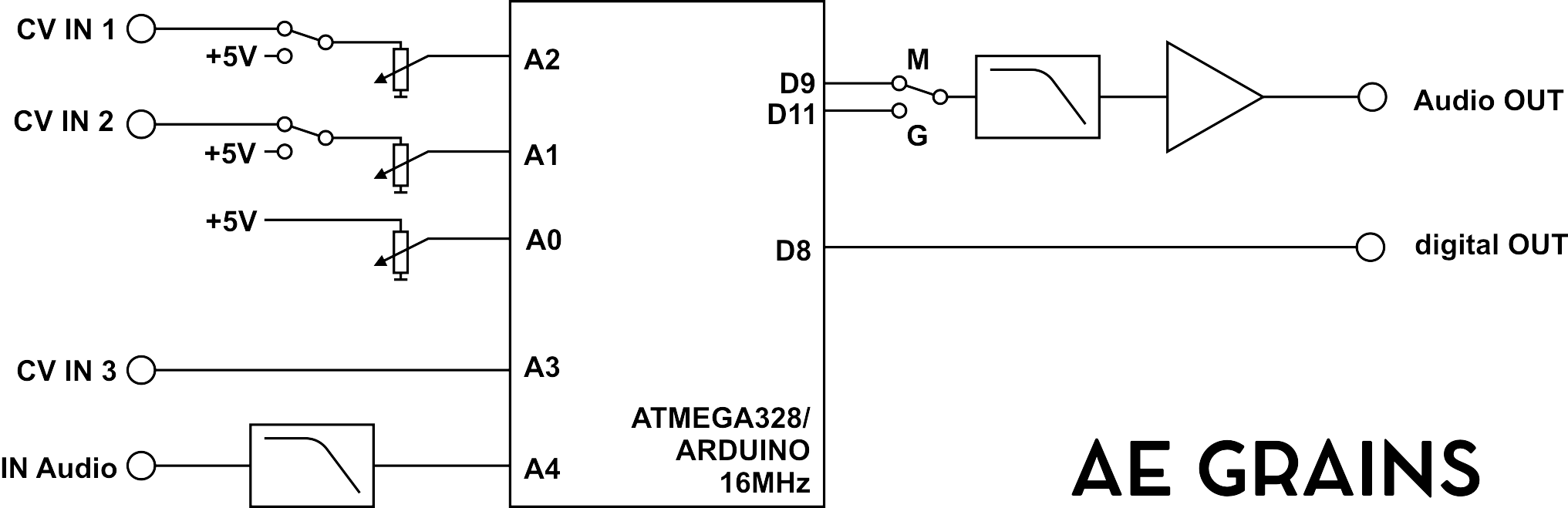
The firmware codes from the Ginkosynthese website are mostly single files with the ending .ino which means that they are Arduino sketches. You can open them in the Arduino IDE by double clicking on the filename.
Once you have the file open in the Arduino IDE you can upload them to the GRAINS module by clicking the Upload icon (depicted as an arrow pointing right).
Once the IDE shows that upload is complete you can disconnect the USB cable and use the GRAINS module with the new firmware.
Developing your own Firmware
Using the existing codes as example you can either make changes to them or develop your own firmware from scratch. The following diagram shows how you can access the various inputs, outputs and controls from within your code:
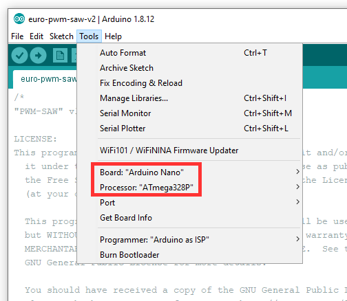
WARNING It is possible to "brick" your GRAINS with certain operations when you develop and test your own firmware programs! This has happened once and you can find how that happened and how it was resolved in this thread on the forum.
Patch examples
This video explains the module in more detail and has some patch examples for various firmwares. https://youtu.be/qpniMuq--M8
There is a section on the forum dedicated to discussing programming this module:-
https://forum.aemodular.com/board/24/programming-grains
Community Firmwares
This code repository contains various firmwares that have been developed specifically for the AE Modular GRAINS module. This has started with the work by German author and software developer Mathias aka @visuellemusik. We encourage you to analyse the code and post your own firmware which we would add to this growing repository. With V2 of GRAINS building your own firmware using the Mozzi Library is possible now, too. With such a firmware the Mode-Switch as explained above and also symbolized in the schematics has to be set to 'M'. Please be aware that some versions of the Mozzi-Library did not work as expected in combination with certain versions of the Arduino IDE. An overview of recommended combinations of the two environments, including prereleases of Mozzi can be found here: https://github.com/sensorium/Mozzi/releases
https://github.com/aemodular/GRAINS
You can download each firmware as an individual zip file or the whole lot from the Release Page.
This video explains how the ByteBeat-Xfade firmware works followed by a little improvised jam. https://youtu.be/Wokre1i8Trg
And this video explains the workings of the SpellOrSpeak firmware, also developed by Mathias. https://youtu.be/a1aS6E0b0Fk
Wonkystuff
This is a new firmware developed by Wonkystuff which brings a Karplus Strong algorithm to the GRAINS module. You can find the code here on Github:
https://github.com/wonkystuff/ks_grains
And this was discussed on the forum here:
https://forum.aemodular.com/thread/1608/karplus-strong-synthesis
Another cool firmware is the Poly Ramp drone oscillator which you can find here:

GRUNGE FILTER
The Polivoks was a Russian synth that was produced between 1982 and 1990.The GRUNGE FILTER is the AE version of the filter that gave the Polivoks a unique, rough sound.
Beyond the basic design, this filter offers some additional features:
-
two different resonance characteristics, hard and soft
-
an FM function, that adds the input signal to the modulation of the filter
-
an optional overdrive for the output, making the sound even more rough and untamed.
-
Power Consumption: 2mA
-
Module width: 1U
Inputs
- IN H - this input is for higher level signals.
- IN L - this input adds some gain to give a higher signal level of the module circuitry, (i.e. low input signals).
- CV 1 - accepts CV control for cutoff frequency
- CV 2 - additional CV control for cutoff frequency
Outputs
- OUT - the signal after being filtered.
- MULT - an unbuffered multiple (a passive bi-directional circuit for mixing/splitting signals).
- BUS CV - this sits below the input jacks on the left side and will output CV pitch from a connected MIDI device
- BUS CTRL - this sits below the input jacks on the left side and will output a volatge dervied from MIDI control message (CC20) from a connected MIDI device.
Controls
- FREQ Knob - Sets the cuttoff frequency of the filter.
- CV 1 Knob - controls the amount CV1 input affects the Cutoff frequency.
- RESONANCE Knob - sets the amount of amplification of the frequencies on/around the cut off point.
- LP/BP Switch - Switches the filter between letting low frequencies past, or also removing/lowering higher frequencies as well.
- DIST switch - Adds an overdrive/distortion to the output signal.
- FM switch - adds some of the main input signal to the modulation of the cutoff point.
- HARD/SOFT switch - changes the overall sound/character of the filter so you get two for the price of one.
Patch Suggestions
With its great sonic character it is highly recommended for bass and lead sounds.
This module does not have CV control of resonance, but it can be created by putting one of the filter outputs through a VCA whose level is controlled by the CV modulation source (e.g. LFO or envelope), then feeding the VCA output back into the same filter - you may need a mixer module, or use a mult if necessary as the levels on the 2 inputs are different. Try the low input for the feed back from the VCA first....
Here are a few videos which show off the great character of this filter:

HEARTBEAT
- Power consumption: 14 mA
- Module width: 1U
Inputs
- CLK - Used to input an external clock source, (e.g. midi from BUS CLK) if needed.
- Reset - ?
- CV1 - Assignable input for a control voltage.
- CV2 - Assignable input for a control voltage.
- Trig 1 - Assignable input for a trigger pulse.
- Trig 2 - Assignable input for a trigger pulse.
The assignable inputs are set by their page in the menu.
Outputs
- BUS GATE - this output gives a +5V signal as long as a key on Midi keyboard, attached via the master module, is held down.
- 1 (x2) - Envisaged as the main clock out, the clock division is set in the menu.
- 2 (x2) - With 2 sockets, 2 is envisaged as the next most used output. The clock division is set in the menu.
- 3 to 6 inclusive - Each is a separate clock out that can be individually set to what clock division in the menu.
Controls
- TEMPO (Encoder) - press and hold to access the menu, and adjust parmeters. Otherwise can be used to alter the tempo of the master clock.
- START/STOP (button) - controls the master clock.
- TAP (button) - this can set the desired tempo by repeated quick presses, (taps); useful for matching to non-midi music.
Display
- 1 to 6 inclusive - these leds pulse in time of the relevant clock signal being output.
The main OLED display shows the temp on normal operation, and also displays the menu parameters when the Tempo knob is held down.
Patch Ideas
Via the use of the external input, this module could be used to divide the midi clock into something more useful for the AE. There is a specific module for this however, the Midiclock Divider. This frees up the Heartbeat to be the master clock for any attached sequencers etc. You may want to take an output from the Midiclock divider into the Heartbeat as well.
The use of a master clock that gives up to 6 different outputs means you could have up to 6 different rhythms/patterns in your drum sounds, sequencers etc.
There is an extender module which gives the use more possibilities:-
https://wiki.aemodular.com/pmwiki.php/AeManual/HEARTBEATEXTENDER

HEARTBEAT EXTENDER
- Power Consumption: 7mA
- Module width: 1U
The HEARTBEAT EXTENDER expands the functionality of the HEARTBEAT module. It is connected to the HEARTBEAT module with a small ribbon cable (included) and offers following features:
- six preset buttons to store and recall different tempos with one button press
- MIDI in and out sockets with LED indicators: The HEARTBEAT module can follow incoming MIDI timing data (MIDI start/stop/clock) as an additional option; and the current tempo of the HEARTBEAT is sent out as MIDI timing data if it acts as master clock in a complete system - other MIDI devices will follow its tempo.
- a knob that controls either the swing amount or the transition time when changing from one preset to another (known as accelerando/ritardando).
- a lock switch, that disable the save button and other functions that could be an issue e.g. in live situations.